


Transmission cooler installation: This unit is attached to the rear of the bumper.
Not shown in the picture is a small shroud that surrounds the cooler to stop air spilling over and around the cooler.
Not shown in the picture is a small shroud that surrounds the cooler to stop air spilling over and around the cooler.

UPDATE INFO: Adding an aftermarket transmission cooler.
The debate over transmission coolers usually involves people looking up Google and posting data based on standard transmissions, and typical pros/cons for adding an external aftermarket cooler, however, there may be other reasons to add an external transmission cooler in the 5AT.
One argument often posted in forums is this: Honda knew what they were doing and designed the transmission warmer/cooler with sufficient efficiency for the V6 5AT, and aftermarket cooling systems are simply not needed: Really?
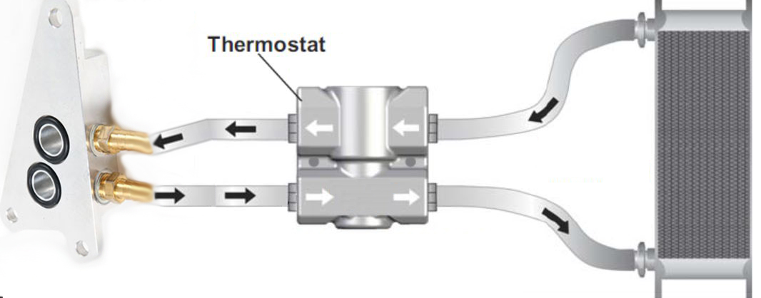
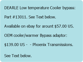
DERALE Fluid control thermostat
OEM Cooler/warmer bypass Adaptor
Using the existing OEM filter and adding an external transmission cooler and temperature bypess valve.
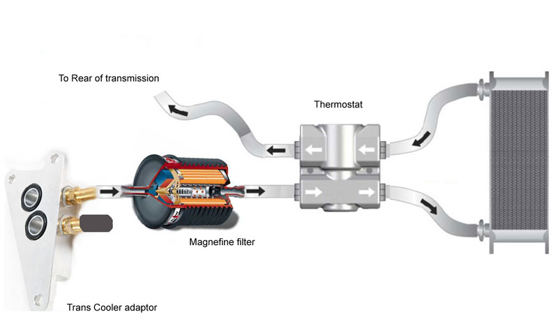
Using a Magnefine filter and adding an external transmission cooler and temperature bypass valve.
So Honda knew what it was doing with Z1 transmission fluid, a small filter they claim never needs replacing and a transmission they claim needs only one partial change of fluid (3L) at 60K or 120K miles, and an ATF cooler system designed before TC overheating faults became evident - Really?
These service intervals and filter recommendations, ALONG with the cooler design, were made BEFORE Honda found they had NOT fixed problems in the 4AT with the 5AT design. They had "alleviated" some but had ADDED others. To quote Honda service interval's and defend "some" design decissions made at that time indicates a lack of knowledge about the 5AT design flaws, basic transmission design, oil function and properties, filter design and Hondas tragic Automatic transmissions history.
I was running a big (to reduce pressure drop) plate & fin transmission cooler. This trans cooler was in series with the existing ATF warmer/cooler, the OEM filter was removed and an external Magnefine filter was used. Over the past few years more information and data has come to light and I have revised my initial decision to leave the ATF warmer in circuit for the following reasons.
Note: Not all models of the 5AT are affected by all of the design flaws, there are variations and changes through models and years. Some models of 5AT with all these condition were used from 2001 to 2006.
1: A number of sources have indicated that the OEM ATF cooler/warmer is restrictive and becomes even more so as the vehicle ages.
2. There is an identified problem in the 5AT transmission with the implementation of Torque convertor and cooler flow circuits. The result is low or NO fluid flow through the Torque convertor (TC) and cooler, the cooler is bypassed and ATF flows directly to the sump at low RPM (< 1500). This is the exact situation for a vehicle in start-stop traffic and idling stationary in D, R or D3. It causes Torque convertor failure from overheating and accelerated clutch pack wear, the heat causes seal deterioration leading to early transmission failure. Test data revelled temperatures in the range of 230-350°F at the convertor output instead of the normal 180°F
3. Data shows that as the transmission ages, cooler flow is reduces to around 0.7 GPM @Hot Idle and 1.2 GPM under acceleration, and dropping near zero when in gear and stationary. The suggested target is to never let the flow rate go below 0.8 GPM under any condition.
4. With this design flaw, any restriction in the cooler circuit makes the condition worse and will result in the Torque convertor (TC) failing even earlier. Remember that Honda implemented Phased engagement of the TC clutch, and at speeds below 40 mph, the TC is already on the edge of implemented lock logic and will be going in and out of lock, the result is high TC temperatures. TCU logic causes the TC to unlock/lock easily, even at highway speeds if you are slightly on or off the throttle, and this gets worse with age due to reduced flow and other design decisions made in the 5AT, the result is this: Every time you come to a stop you may have minimal flow through the TC causing it to overheat - 230-350°F.
Of course some of you will want to follow Hondas advice and leave the old clogged transmission filter in forever - Are you sure you want to do that? - IMHO the filter bypass won't save you from this defect. When I was testing flow through the old filter, I found it required quite some pressure to unseat the filter bypass, now that could have just been my filter, but what is your filter like?
The initial decision to leave the OEM cooler/warmer in circuit was based on the need for ATF to reach a desired target operating temperature. Shift logic, shift feel and TC lock parameters are modified by the TCU as it monitors ATF temperature. However tests indicate that this is not a problem without the OEM unit if a Temperature bypass device is included in the External cooler circuit. With this in place and due to heat generated by the TC, the ATF heats quickly when the cooler is bypassed.
See - Using the Existing Cooler/Warmer:
There are two ways to remove the existing cooler/warmer. There is a low cost modification to the "Filter Body Housing" that you can attempt yourself and was shown here in 2007 LINK to Forum. Some countries cannot get the filter housing and if they can, the cost outside of the US can be up to $80.00. You need to be able to get this part if an attempt to modify the existing housing goes wrong.
There is an aftermarket adaptor, but it's more expensive at around $130.00 LINK to adaptor. With this adaptor, you simply remove the existing Hockey-Puck warmer/cooler and bolt the adaptor in place. There are two fluid connections, one is hot fluid direct from TC / Transmission, the other is an Inlet into the back of the existing filter housing assembly.
As I have the transmission cooler already plumbed to the ATF Inlet port at the rear of the Transmission, the only connection I need is fluid Outlet. Due to my external Magnefine filter, the OEM filter housing will no longer be used, this now gives me a direct path to the External Filter and Cooler without the current twisted path through the OEM cooler and (empty) Filter housing and its associated Banjo connection. A temperature bypass unit is mounted down low near the external cooler and does not require any changes to the fluid line lengths or routing when installed.
I will be plotting/tracking ATF and Coolant temperature directly from OEM inbuilt sensors to test how long this new setup takes to bring ATF into the target range.
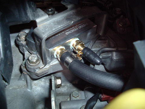
The OEM cooler/warmer External cooler Adaptor mounted on the existing Filter body Housing.
I'm using the outlet port only as I have an external mounted Magnefine filter.
Right: OEM ATF warmer / cooler removed. It sits on top of the filter adaptor body.
This is the underside of the device, the two underside ports are for ATF inlet and outlet. The pipes on either side connect to the engine coolant outlet and inlet.
When permanently removing this device, the engine coolant inlet and outlets are connected together with a short piece of tubing.
Note: Coolant must be drained first, the coolant lines disconnected and engine coolant inlet and outlet connections bridged with a short piece of hose. Cut one of the old connection hoses to do this.
WARNING: Coolant must not be allowed to enter the ATF ports of the filter adaptor body. This is why coolant mods must be completed first. It's also important to tape over the old OEM warmer coolant tubes and stop coolant from spilling out of the old warmer as it's removed, it could flow into the ATF ports.
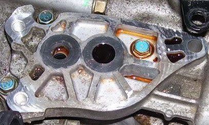
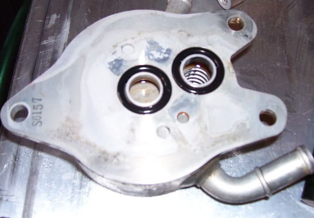
View of part of the filter adaptor body after the OEM warmer (above) has been removed (NOTE this is not my transmission or picture).
The left port is the ATF outlet port from the transmission, the right port is the inlet to a passage the enters the back of the OEM filter housing. As I use a Magnefine filter I don't use this fitting or the OEM filter.
The left port is the ATF outlet port from the transmission, the right port is the inlet to a passage the enters the back of the OEM filter housing. As I use a Magnefine filter I don't use this fitting or the OEM filter.
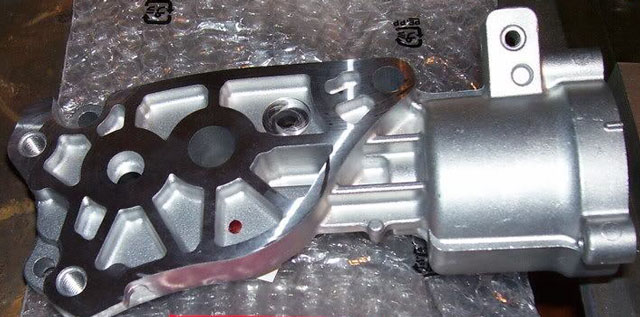
View of a new filter adaptor body for reference.
Hopefully this will make what I'm referring to in the picture above a little clearer.
Hopefully this will make what I'm referring to in the picture above a little clearer.
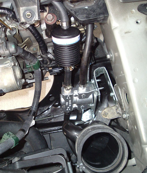
Rough view (before final trimming of brackets and screws) of the external mounted Magnefine filter connected to the outlet port shown above, some slack in the hose between the filter and the outlet is needed to allow for engine movement.
The DERALE Fluid control thermostat (Low temp Cooler bypass) is shown mounted below the filter.
The hose on the right is the ATF return hose running directly to the ATF input connection on the rear of the transmission.
This view is with the Battery and battery mounting plate removed. The top section of the cool air intake duct has also been removed.
It would be easier to use the existing filter and housing, as fitting the Magnefine in this confined space, while leaving sufficient room for slack in the hose connections, is not that easy.
When using the existing Filter and Housing, the connection on the Right of the temperature bypass would simply connect to the Inlet port of the OEM Warmer removal adaptor. The port shown closed off in the picture above.
I've been monitoring ATF temperature directly from the inbuilt ATF sensor and comparing it against ATF input temperature and Coolant temperature. It appears that the tiny OEM warmer/cooler is going to take a long time to bring down ATF temperatures, especially when faced with high Torque Convertor output temperatures - very common in stop start driving.
Some of the 5AT rebuilders have been so concerned about this TC problem that even after a rebuild and internal cooler circuit modifications, they not only recommend adding an external front mount transmission cooler, but because of the cooler circuit flaw, now recommend removing or bypassing the existing warmer to reduce cooler flow restriction and bring down/control ATF temperatures, some have made an adaptor available for this purpose.
For a number of years, I've had a large external trans cooler connected in series - after the warmer - and recently added a temperature bypass device that bypasses the external cooler until ATF output temperature reaches 82° C - 180° F.
I started plotting ATF and coolant temperatures over a number of identical 20 minuted drives and repeated the tests after removing (bypassing) the OEM warmer. For the past few weeks the temperature here (not that cold) had been around 16° C with a cold wind. ATF temperature difference after removing the warmer are: After 3 minutes 3° C, @ 5 minutes it's 3° C, @ 10 minutes its 10° C and after 20 minutes there is a 6° C difference. Basically the external cooler is bypassed the whole time and ATF warm up is still quite fast.
Looking at the TC lock command via OBD shows the TCU outputting a command at around 32° C, which I found surprising as I thought it would be closer to 60° C - 140° F before TCU logic considered ATF warm enough? After all, the OEM warmer is supposed to heat ATF to around 86° C over time and will not start removing / controlling heat until the ATF is around 96° C - 204° F.
One thing that I have confirmed is this TC lock hunting issue when driving in D at speeds below 45 mph. The TCU is constantly commanding TC lock but I/O (difference between Input - engine RPM and Output - main shaft RPM) speeds are rapidly changing in traffic along with engine load causing the TC command to be repeatedly started and stopped. Without access to other information I can't know what is happening with the lockup timing valve or control valve, and hence, what state the TC clutch is in and how much pressure is being applied to the clutch. Other writers and transmission techs have stated for a long time that this contributes to TC clutch failure and trans overheating issues.
Shifting to D3 below 45mph "dramatically" reduced the occurrence of TCU lock commands that I was seeing, this has long been suggested as a way to keep the TCU TC programming logic in a favourable zone for these lower speeds. A pratcise I have used for years.
Another thing I noted was that instead of immediately sending an unlock command, the TCU appears to hold the lock command, even though TC I/O speed is quite high and engine load is changing. Obviously the TCU sees a driver ease up on the throttle - no brake and what looks like a coasting or holding situation, so it holds a lock command, however it appears to lock way to quickly, without waiting long enough to see if this state is going to be maintained? This really seems to be poorly implemented logic in TCU programming for TC Lock control, and especially so at slow speeds in D.
One thing I should point out is the need for a BIG external stacked plate or plate and fin cooler. If you have a smaller cooler then unless it's fan assisted at slow speeds, or especially when stationary, like stop start driving, there is a very high probability of high ATF temperature with little air flow over a small cooler in hot conditions. I have found that the AC fan is suffieicnt with this big cooler.
A number of transmissions rebuilders are now using an adaptor like the one I posted, they remove the OEM unit and add an external cooler when they modify and rebuild the 5AT transmission. It will be interesting to see if this air flow heat issue at slow speeds is true, at least in my case, but I do have a very big plate and fin cooler and as I run the Climate control at all times, I most likely have enough stationary air flow from the AC fan as is.