Modifying the HVAC - Dual Zone Climate control PCB
Work in progress update - I decided to attempt to cut the size of the HVAC/Audio interface board to a smaller size. I spent over two days just tracing every connection from the lower half of the board back to the HVAC Micro - that was after I identified which IC was actually the HVAC micro - there is no data for two of the three microprocessors on this board.
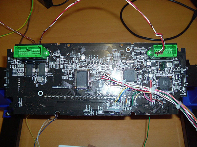
The picture on the left shows the OEM PCB, that board extends to the bottom of the picture below the plastic cover.
The picture on the right shows the cut down board running on the bench. The connections go to a small interface microprocessor that has a USB connection to a tablet or PC and is completely controlled via my HVAC software. I have also removed the LCD display on the opposite side of the board, this leaves room for my interface Micro to mount, the idea is to keep the whole package as small and as thin as possible. This unit can also be controlled in standalone mode, (no PC) via a small radio remote control which can be fitted anywhere, it displays temperature and full HVAC status on a small $14 two line LCD.
I

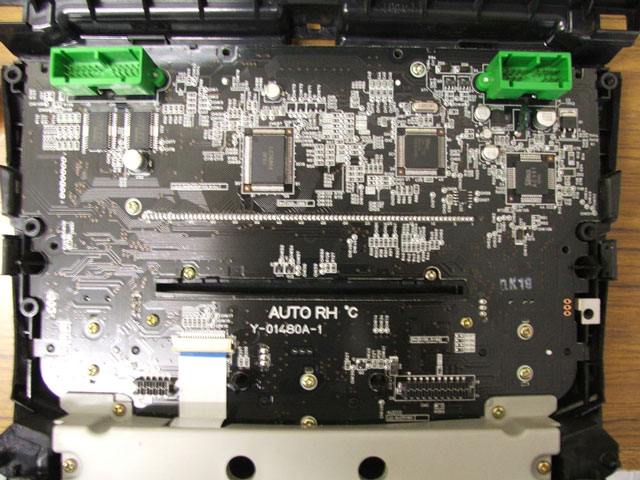


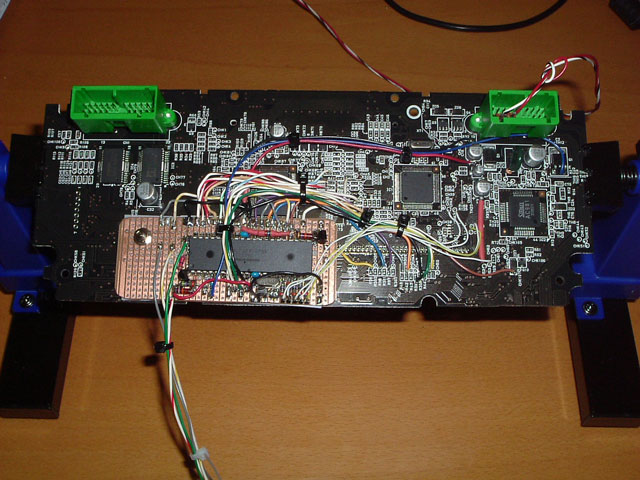
Back of HVAC/Audio PCB with the LCD removed.
Still have a few lamps and switches to remove.
This will allow the board to sit right at the bottom of a case, making the case height quite small.
Still have a few lamps and switches to remove.
This will allow the board to sit right at the bottom of a case, making the case height quite small.
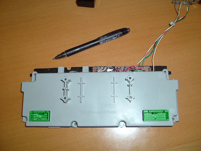
RIGHT: With the oroginal plastic cover in place.
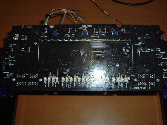
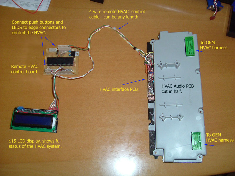
Again the only connection to this unit for every function, switch and LED needed to control the HVAC in standalone mode (no PC) is the 4 wire lead coming out at the top.
This will soon go to a small 5 pin socket.
No Radio - 6 CD stacker required.
The upper dash is now free to take whatever you want to put there.
HVAC interface micro wired up.
I changed my mind and mounted the Micro board on this side of the PCB to allow for short connections. I decided to solder to the underside of the Veroboard to make it as small as possible, easy to wire up and to fault find.
The 4 wires running away from the board are for serial TX, RX ground and an optional 5v.
Plug the vehicle HVAC leads back into the green sockets and its ready to go.
The top lead is 12v supply that is normally supplied via the OEM HVAC harness.
SEE: -> Technical Data
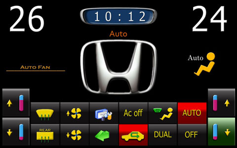
Screen grab of the Car PC Climate Control software
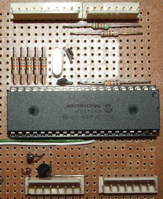
ABOVE is a rough idea of how hard the HVAC interface micro PCB is to make. Note: The sockets along each edge are not needed.
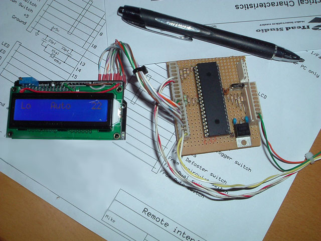
<- LEFT is a picture of the Remote board, I had an old Arudino Shield that I used for the LCD display. HVAC switches and 5 LEDS are simply connected to the sockets on the PCB. Once again just a few resistors and a 5v regulator.
Could not get a good picture of the display.
<- LEFT is a picture of the Remote board, I had an old Arudino Shield that I used for the LCD display. HVAC switches and 5 LEDS are simply connected to the sockets on the PCB. Once again just a few resistors and a 5v regulator.
Could not get a good picture of the display.
How it all goes together - Standalone full HVAC control, OEM Radio/CD and Head unit fully removed.