
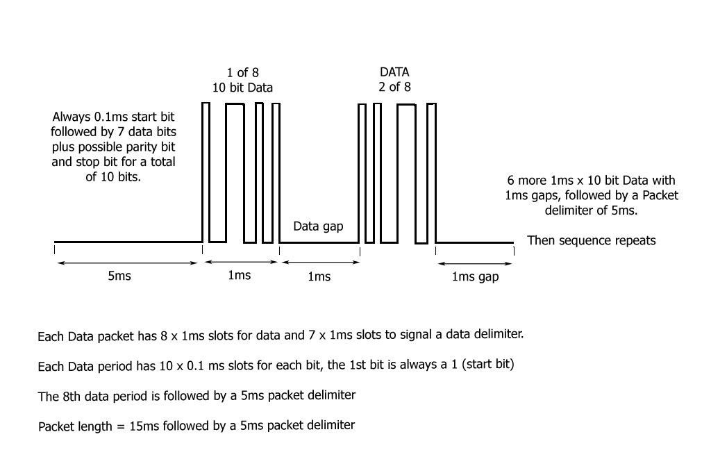
HVAC Data stream, information from my digital storage Scope. This stream transmits temperature, Vent position and diagnostic data only.
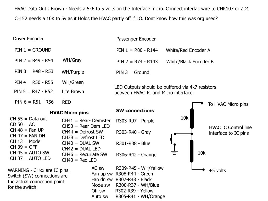
OEM HVAC PCB connections - Needed for external interfacing
NOTE: Wire Colours are ones I used in my prototype. Encoder Pin numbers refer to the OEM Encoder pin designation on the PCB - that part of the PCB has now been cut off.
With this Circuit the HVAC is now fully controlled via:
1: A small remote control device that can be wired or plugged into the 4 wires coming from the modified HVAC board (Or a low cost Wireless link = No wire conections).
2: Software on a PC with full touch screen control and display of everyl HVAC function.
3: Both 1 & 2.
All firmware for the microprocessor interfaces is free and will be posted here soon.
Modifying the HVAC - Dual Zone Climate control PCB
On the Left:
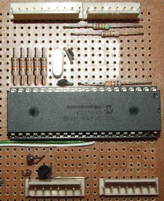
Rough idea of how hard the HVAC interface micro PCB is to make.
Note: The sockets along each edge are not needed.
Rough idea of how hard the HVAC interface micro PCB is to make.
Note: The sockets along each edge are not needed.
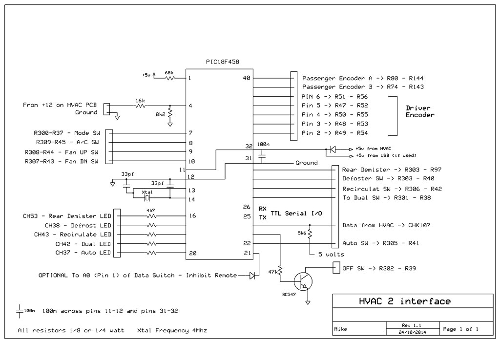
Microprocessor interface circuit:
All parts are low cost and easily available, most from Jaycar. Only 4 connections leave the modified case - Serial Data TX & RX, +12v and Ground. If a USB to serial cable or module is used (for Computer control) then an optional 5v from the USB line is used.
All parts are low cost and easily available, most from Jaycar. Only 4 connections leave the modified case - Serial Data TX & RX, +12v and Ground. If a USB to serial cable or module is used (for Computer control) then an optional 5v from the USB line is used.
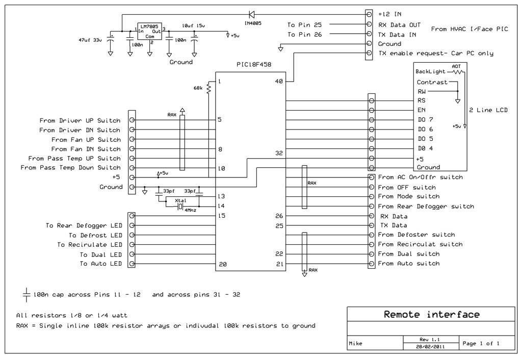
REMOTE interface circuit:
All parts are low cost and easily available, most from Jaycar. Only 4 connections leave the modified case - Serial Data TX & RX, +12v and Ground. If a USB to serial cable or module is used (for Computer control) then an optional 5v from the USB line is used.
All parts are low cost and easily available, most from Jaycar. Only 4 connections leave the modified case - Serial Data TX & RX, +12v and Ground. If a USB to serial cable or module is used (for Computer control) then an optional 5v from the USB line is used.
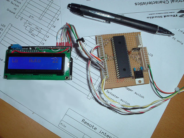
A picture of the Remote board, I had an old Arudino Shield that I used for the LCD display. HVAC switches and 5 LEDS are simply connected to the sockets on the PCB. Once again just a few resistors and a 5v regulator.
Could not get a good picture of the display.
Could not get a good picture of the display.