Wire Type K Thermocouple: Jaycar CAT. NO. QM1283 - $7.50 US
NOTE: Needs this Thermocouple Amplifier AD595-AQ $17.50 US from Sparkfun.com to interface with anything.
OR a ready to go 2 input thermo meter : (Includes thermocouples) Jaycar CAT. NO. QM1601 - $50.00 US
NOTE: Needs this Thermocouple Amplifier AD595-AQ $17.50 US from Sparkfun.com to interface with anything.
OR a ready to go 2 input thermo meter : (Includes thermocouples) Jaycar CAT. NO. QM1601 - $50.00 US


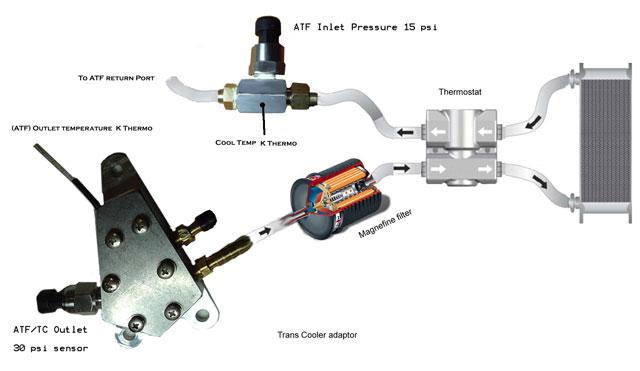
Derale 13021 -6AN x -6AN In-Line Fluid Thermostat:
On line eBay, Amazon etc: Around $30 to $40.
I uses this as an inline adaptor for a 15psi sensor AFTER the cooler and filter.
Unscrew temperature switch and tap case to take the pressure sensor thread.
Below the basic after I modified the Cooler Adaptor for TC output Pressure
using a 30psi sensor and TC/ATF outlet and a 15psi at the return ATF connection after the cooler, temperature bypass adaptor and filter.
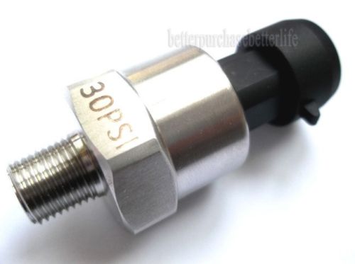
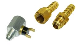
ATF pressure sensor:
30psi Sensor: $22.00.
15psi sensor is the same.
30psi Sensor: $22.00.
15psi sensor is the same.
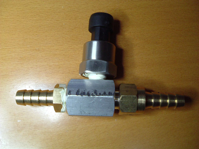
Return ATF P-sensor mounted on a Derale 13021 Inline fluid adaptor shown below.

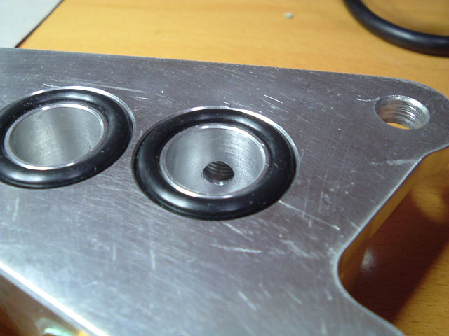
Inially I could see no way to fit a Pressure adaptor at the ATF/TC outler port (no room) I then realised I could modify the OEM cooler bypass adaptor and fit a Pressure transducer and K-Thermo in the housing. This makes for a robust installation with no extra hose fittings, clamps or restrictions. I drilled a small hole from the back of the adaptor into the outlet cavity then opeaned the small hole up for 3/4 of its depth and tapped it for the larger Sensor thread, Picture below shows unmodified Adaptor top and Psensor installed .
While I had the adaptor out I came up with a neat way to add the K-Thermo temperature sensor into the ATF outlet stream. In the picture below left I have drilled a tiny hole in a recess in the top of the fluid cavity, you can see the Pressure sensor opening at 2 oclock in the same picture. If you look closely you can see the head of the K-Thermo in the bottom of the recess. The aluminium housing is about 1/4 inch thick at this point, I forced high temperature silicone R.T.V gasket rubber into the hole from behind the sensor. A cover plate was made and screw holes tapped into the top of the housing for this plate. The top of the Adaptor housing is covered with High temp Silicone RTV and the cover is screwed down. The wire form the K-thermo is covered in a fibreglass sheath so compressing it causes no harm.
Having the K-Thermo directly in the ATF outlet stream is critical if you want to catch Short duration TC spike temperature that cannot be recorded any other way as any fault causing TC overheating at very low RPM in gear while stationary will be flattened or completely missed. IE: A metal tube and K-Thermo tightly coupled to it with the whole assembly wrapped and insulated could not catch even normal smaller spikes in TC outlet temperature as the duration is less than a second once full fluid flow increases with rising RPM.
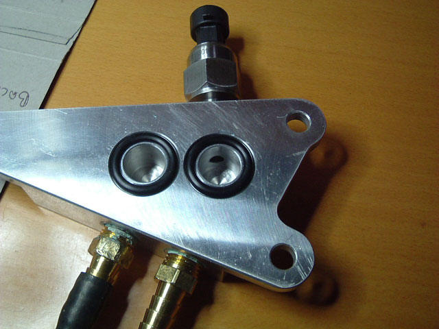
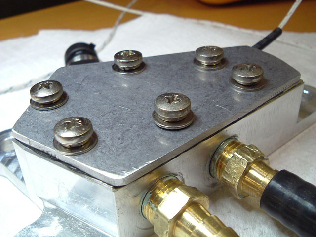
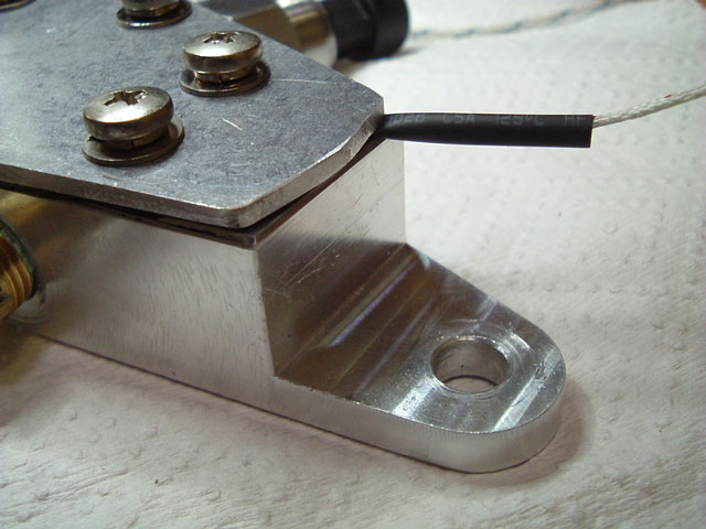
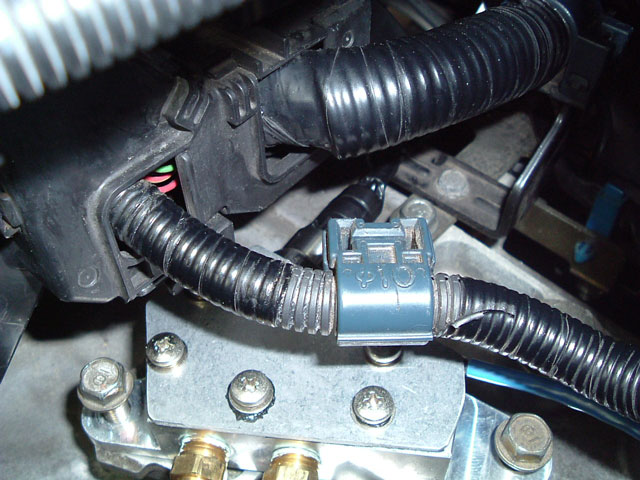
I initially monitored ATF temperature by inserting the tip of a K-Thermo into a "tiny" hole in the Rubber ATF line, after sealing the K-thermo and hose I tested it to quite high pressure and there was no leak. I had not counted on the rubber becoming quite soft with heat and after a while I could see a stain starting to appear on the K-Thermo exit lead. This new installation is perfect so far, as you see from the pictures below I went over kill on the top sealing plate, the lead runs from above the port on the left across the top of the housing below the cover plate and exits at the right hand side of the picture. Again, the area between the cover plate and the housing (cable runs through) is filled with Silicone R.T.V gasket sealant.
Having the K-Thermo directly in the ATF outlet stream is critical if you want to catch Short duration TC spike temperature that cannot be recorded any other way as any fault causing TC overheating at very low RPM in gear while stationary will be flattened or completely missed. IE: A metal tube and K-Thermo tightly coupled to it with the whole assembly wrapped and insulated could not catch even normal smaller spikes in TC outlet temperature as the duration is less than a second once full fluid flow increases with rising RPM.
I initially monitored ATF temperature by inserting the tip of a K-Thermo into a "tiny" hole in the Rubber ATF line, after sealing the K-thermo and hose I tested it to quite high pressure and there was no leak. I had not counted on the rubber becoming quite soft with heat and after a while I could see a stain starting to appear on the K-Thermo exit lead. This new installation is perfect so far, as you see from the pictures below I went over kill on the top sealing plate, the lead runs from above the port on the left across the top of the housing below the cover plate and exits at the right hand side of the picture. Again, the area between the cover plate and the housing (cable runs through) is filled with Silicone R.T.V gasket sealant.
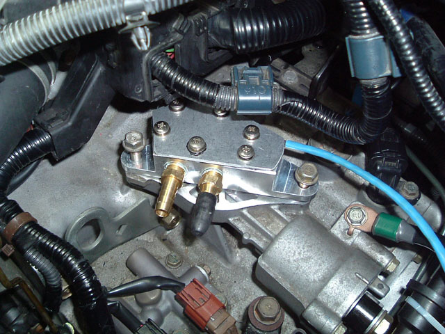
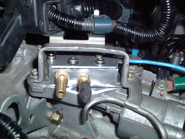
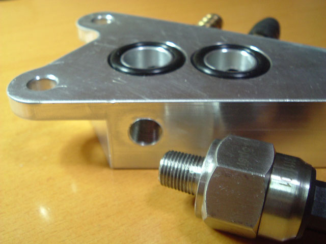
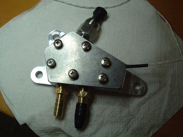
Above left is OEM cooler bypass Adaptor installed without Transmission vent and cable stay bracket. Above right is a view that shows - just - the 30psi ATF exit pressure sensor at the rear of the adaptor, no interference to cables or any other component - perfect, protected and safe.
Below is the fully installed adaptor.
Below is the fully installed adaptor.
I have at last modified the cooler outlet Temperature sensor and Pressure sensor housing and now have a K-Thermo sensor-head directly located into the ATF stream and completely isolated from the metal housing.
The reasons for this are explained in the Cooler testing page. and Testing Recap page.
The housing had been drilled and tapped either side for both a Temperature and a pressure sensor. This is quite a chunky block of aluminium and neither the Pressure sensor nor Temperature adaptor quite reach into the "fluid flow through" section of the housing. In other words nothing impedes flow or reduces the internal diameter of the inline fitting.
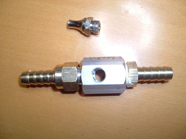
I tapped the opposite side of the housing with the same thread as the Temperature sensor - 1/8 NPT 27T - to take an Air duster fitting after removing the long air tube.
The fitting has a small opening at what was the Air exit and a larger opening into the threaded end.
Filling this shaped fitting with High temperature Silicone R.T.V. helps it act like a sealing plug along with supporting the K-thermo head and lead for a no leak sealed sensor probe.
The fitting has a small opening at what was the Air exit and a larger opening into the threaded end.
Filling this shaped fitting with High temperature Silicone R.T.V. helps it act like a sealing plug along with supporting the K-thermo head and lead for a no leak sealed sensor probe.
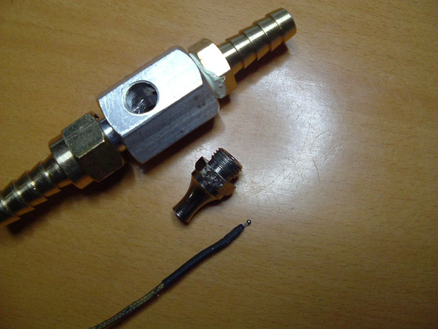
Tiny K-thermo sensor head and lead before fitting into the old Air Duster fitting.
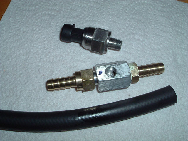
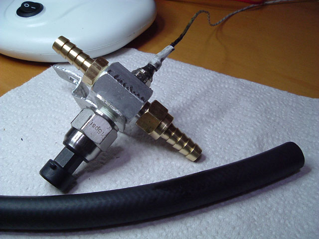
Pressure Sensor and Housing next to 3/8" ATF hose to give a better size of the fittings.
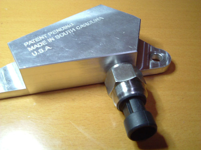
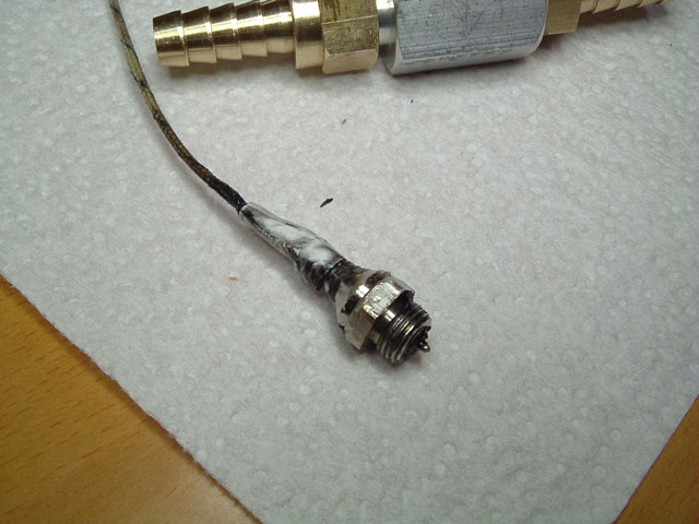
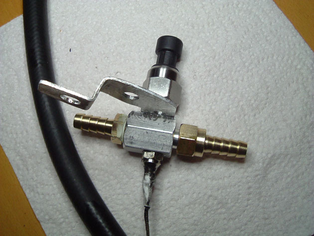
End and side views of the finished Sensor probe.
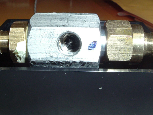
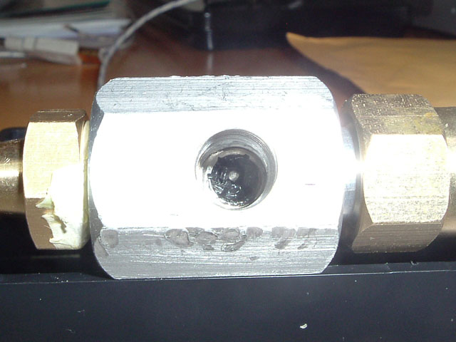
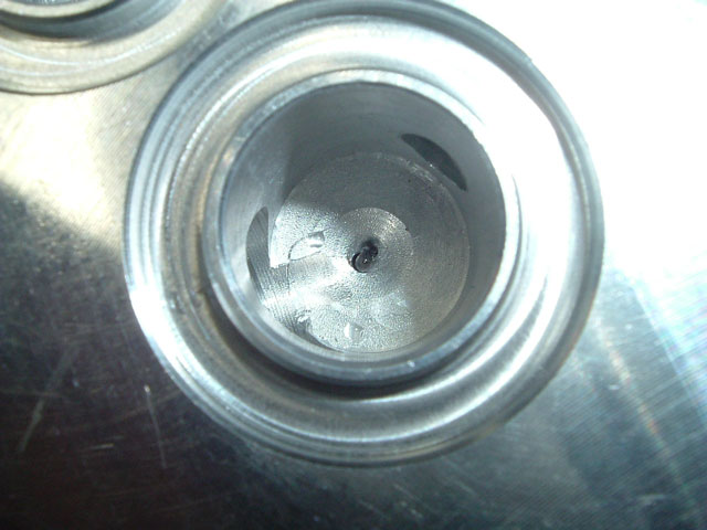
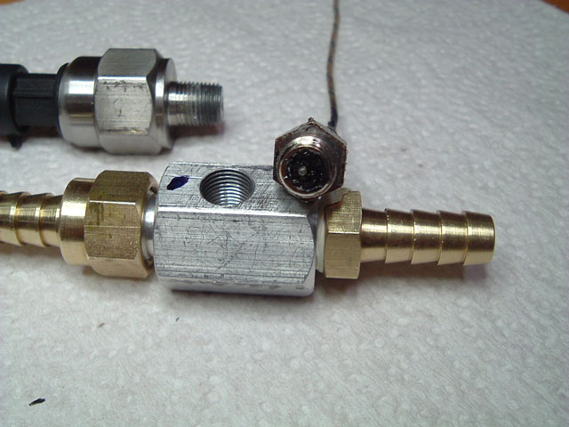
Best I could do of a view into the opposite side of the housing looking at the Temperature Sensor. The sensor tip sits just below the inside diameter of the fluid passage - it does not impede ATF the flow.
Note: Air-D = Air Duster Housing. The K-thermocouple is mounted and sealed in the Air-D fitting with high temperature silicone RTV. The idea is to get the tiny sensor head positioned in the middle of the opening in the Air-D housing and slightly proud of the RTV and Air-D surface. This allows the sensor head to be in full contact with the ATF stream.
1: Keep all RTV away from the head.
2: Fold and then trim back the outer fibreglass covering the sensor lead, trim about 3/4".
3: Now trim the two inner coverings back to expose the two metal leads for about 1/2".
It's important to remove about 1/2" of the two inner cable covers, the metal leads should stay seperated - adjust if they touch - and can now be packed and covered with RTV, this should stop ATF from leaking up the inside of the cables. Force RTV into the uncut outer sheaths as well. With the lead inserted through the Air-D adaptor and about 1/2" left before the sensor head is in position, fill and pack the Air-D housing with RTV, as the lead is pulled through continue to pack the housing until the sensor head is in its final position. I then heat the housing with a Hot air gun (not really necessary) to start it curing and wait about 1 hour for the RTV to skin and slightly set internally.
Cover the cable exit on the housing with RTV, be careful not to move the sensor or sensor cable. Place a 1" piece of small diameter Heat-shrink tubing over this mess. Cover this tube and the outside neck of the Air-D adaptor with RTV and fit a larger piece of Heat-shrink tube over the Air-D housing neck and pack with RTV as you go, wait about an hour before heating the tubing with a hot air gun or soldering iron to shrink it. It should clamp around the neck and both hold and seal the cable at the exit point.
Place the fitting in the sun or a warm area for 5 or 6 hours. Wait at least 24 hours or more before installing the fitting to ensure all RTV has cured.