


Adapting the OEM ATF Sensor for independent SUMP ATF temperature information
Honda AT data is usually not available via low cost aftermarket OBD2 readers, it is propriety data and usually only available via the OEM HIM and HDS (Honda & Acura Diagnostic System) software.
Expensive aftermarket readers area available with OEM upgrade packages to display various OEM systems, systems start at around $500 and go upwards. OEM HIM or clone variation that runs HDS software are available from $30 to $180 and come with a version of the Honda HDS software. The HIM was changed by Honda in recent years and older versions will not work on newer Vehicles, however for models from pre 2000 to 2009 or so still use the HIM interface module and software.
Normally you have only two option to read ATF Sump temperatures:
1: Purchase a clone or aftermarket reader - one that can access non standard AT data - and monitor via OBDII.
2: Add a temperature gauge and a sensor to the Sump - most do this, but do so incorrectly.
A third option is to find a way to utilise the OEM ATF temperature sensor independently of the OBD2 network, this is what I have endeavoured to achieve. However you must NOT load the existing Sensor circuit, if you do, the data sent to the TCU/ECU will be incorrect.
You need a Hi Impedance meter like a DVM, or a Micro processor with a high resistance input.
The cost of doing this can be as little as using a $20 DVM (Digital Volt Meter) and my look up chart. For something a little better you can use a Windows Laptop/Tablet, a small Microcontroller interface and Windows ATF display Software, this will allow you to display ATF sump temperatures directly on screen. I will be making the Windows ATF display software FREELY available and will also make the Firmware and simple circuit available to anyone interested. Cost of Microcontroller and components should be less than $30.00 and involve soldering only a few wires.
Another option is to use a $40 small ( 2" x 2") Micro Computer and drive an LCD display screen directly or a small $12.00 2 line LCD display as I have now codeed the Voltage to Temperature function into the small micro. This micro can also be connected to an SD card socket, allowing you insert an SD card and log temperature data to the card for later viewing in Chart software on a Windows computer. I have programmed micro to accommodate two X pressure sensors, two X K-Thermocouples temperature sensors along with the OEM ATF sensor.
How to you use this sensor and why you can't just hook it up to an aftermarket Temperature Gauge.
The ATF sensor in the Honda, and most Vehicles, is an NTC Thermistor - Negative temperature coefficient temperature sensitive resistor. Being an NTC implies that resistance lowers as the sensor warms, resistance is high when cold and low when hot, therefore in this setup the voltage drops with increasing temperature. The maximum and minimum voltages for the sensor in the Honda are 4.93v and 0.07v, outside of this an AT code will be set for ATF Sensor open or short.
One of the problems with a Thermsitor is that it's a nonlinear device and requires manufacture data for mathematical equations to even begin to utilise the device. I cannot find any data or specification for this sensor that have the required parameters for math calculations.
Ok, let's cut to the chase: I devised a simple way to measure exactly what the vehicle TCU/ECU sees and tabulate the Voltage, Resistance and Temperature of the device in circuit in 5°C steps from -20°C to 150°C. This allowed me to build a lookup table in human readable form and calculate finer 1°C degrees of temperature between each °5C step if needed - I've already coded it in my software.
These value were still not sufficient for me to plug into any existing formula, however I simply implemented a look up table in Software with 1°C resolution and I'm happy to say that it works perfectly and so far tracks ATF temperatures displayed with a Honda HIM via OBD2.
With the following Lookup Table and a $20 DVM you could preform a quick monitor of transmission sump temperatures in order to check that you are not running HOT when towing, steep hilly driving or long periods in stop start traffic. Sump temperature gives you an IDEA of long term ATF temperatures but will not reveal very high short term TC outlet temperatures which are a hidden danger in this 5AT.
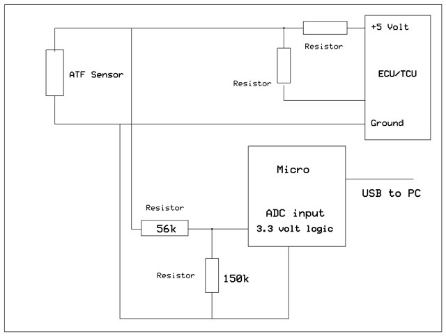
Basic idea of the connections to a MicroComputer.
The top half of the drawing is the existing connections.
The lower part - Micro, 56k and 150k resistors - are the interface.
The top half of the drawing is the existing connections.
The lower part - Micro, 56k and 150k resistors - are the interface.
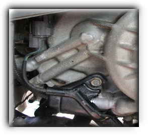
The Gray plug - top left - is the ATF temperature sensor connector. Remove LH wheel for easy access.
I connected to the cable on the lower side of the plug as this is the connecting lead to the sensor - which is replaceable - this leaves the vehicle wiring loom untouched. I sealed the connection with Silicone RTV and wrapped in tape for a water tight connection, tape was also coated and sealed.
I connected to the cable on the lower side of the plug as this is the connecting lead to the sensor - which is replaceable - this leaves the vehicle wiring loom untouched. I sealed the connection with Silicone RTV and wrapped in tape for a water tight connection, tape was also coated and sealed.

OEM ATF temperature sensor Lookup Table Data
Resistance values are in ohms unless indicated otherwise.
R = Resistance k = kilohms 4k7 = 4.7 kilohms
Resistance values are in ohms unless indicated otherwise.
R = Resistance k = kilohms 4k7 = 4.7 kilohms
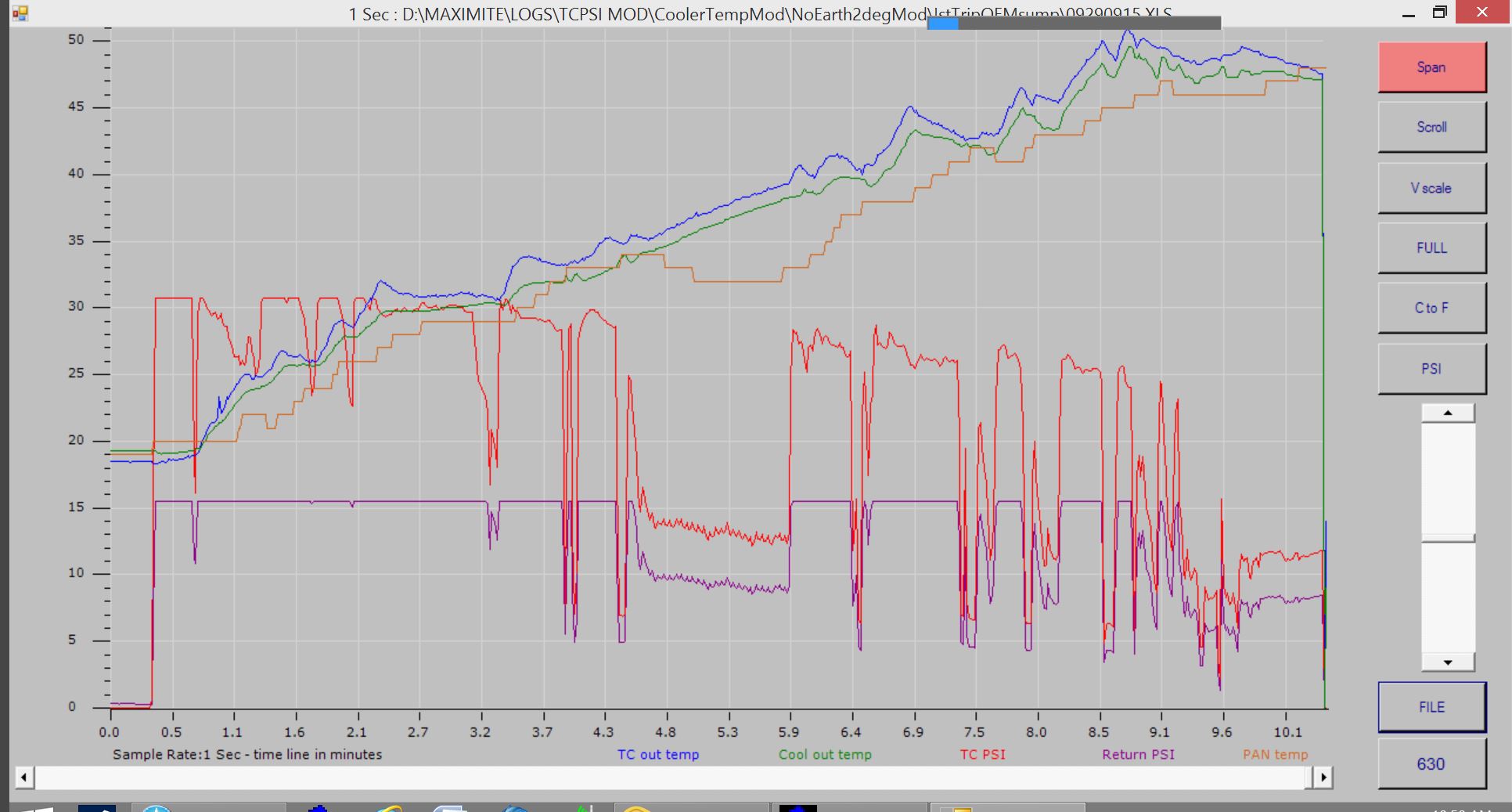
First run with the OEM sump sensor: Note the OEM Sensor has a response time measured in seconds and the Pan (sump) temperatures change more slowly than the TC or cooler outlet temperatures AND those two sensors are Thermocouple devices and have a response time of a few milliseconds. The result is a stepped waveform from the OEM sensor, but gee it tracks well and does exactly what I thought.
Also of interest is Sump temperatures starting to come down @ 4.5 minutes as the transmission cruises in 5th even though ATF temperatures are still increasing. The Sensor is been influenced by the AT outer case being cooled 2° to 3° by high speed air flow over the case / sump and under the influence of lowered ATF flow. It starts to rise again just before dropping to 3rd because of rising ATF temperatures and then higher ATF flow rate (which overcomes AT case influences) along with slower speed and heat increase from the TC as the vehicle accelerates up an incline .
Also of interest is Sump temperatures starting to come down @ 4.5 minutes as the transmission cruises in 5th even though ATF temperatures are still increasing. The Sensor is been influenced by the AT outer case being cooled 2° to 3° by high speed air flow over the case / sump and under the influence of lowered ATF flow. It starts to rise again just before dropping to 3rd because of rising ATF temperatures and then higher ATF flow rate (which overcomes AT case influences) along with slower speed and heat increase from the TC as the vehicle accelerates up an incline .
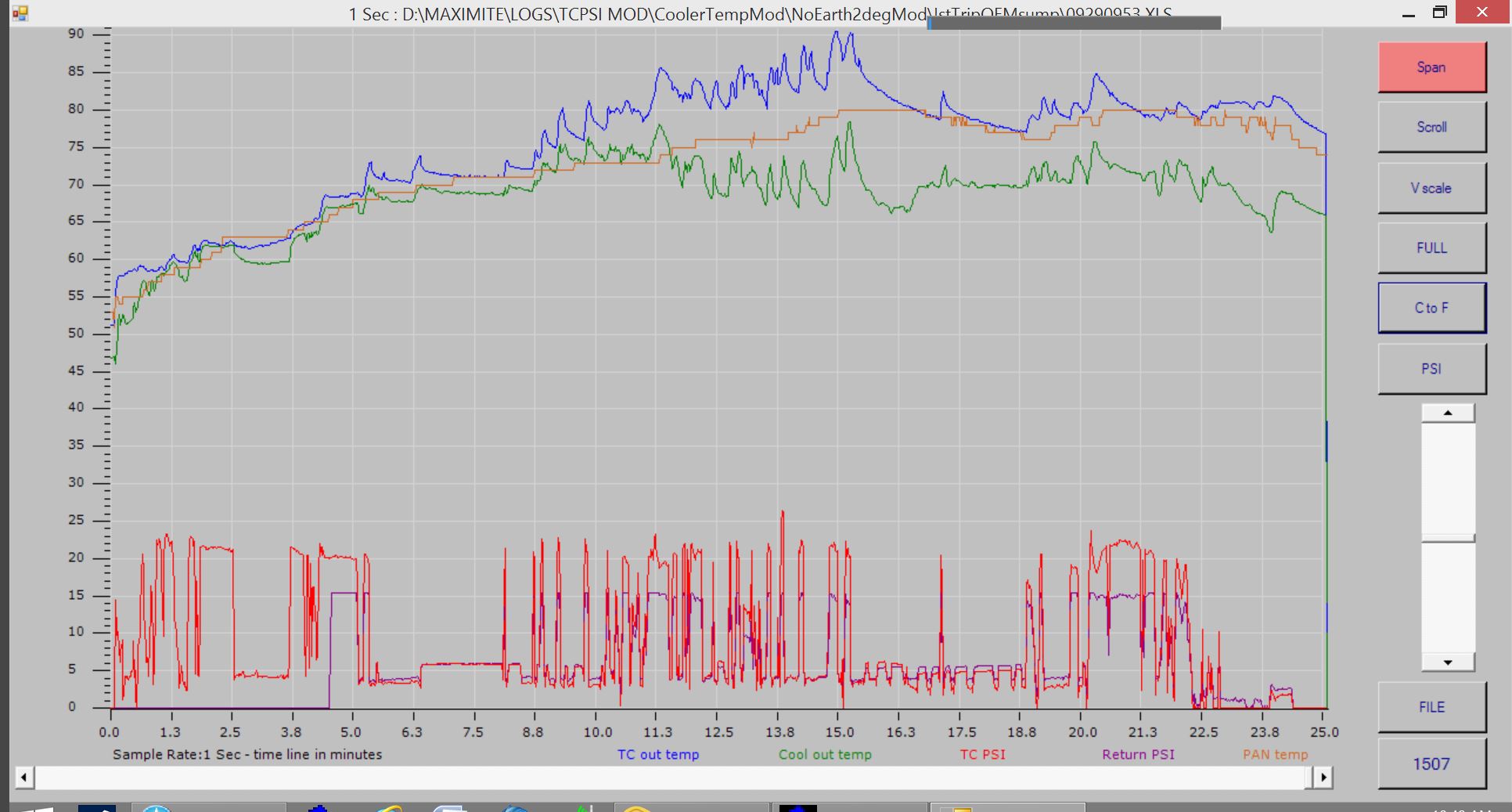
The graph below carries on from above, I stopped for a while and then drove through some twisting hilly roads, left the Transmission in D up a few steep hills (instead of D3) to increase TC outlet temperatures which makes the TC work harder when climbing. Again the OEM sensor values and my Lookup table confirm the accuracy of my calculations, pretty dam good I think.
It also gives a better idea of OEM ATF sensor tracking once the Cooler Bypass valve opens at around 80°C [TC outlet temp]. Cooler outlet temperatures then drop way below Sump temperature and TC outlet matches OEM Sump sensor temperatures whenever the TC is not generating heat - IE cruise locked or flat road easy driving with no start stop conditions. Note: Very hilly twisting road with lots of gear changing just after Bypass valve opens. I purposely left the trans in 4th, 5th instead of dropping to 3rd when climbing these hills to force the TC outlet temperatures up.
It reinforces my thoughts on the validity of reading TC outlet temperatures and that once the AT case is warmed to operating temperature, TC outlet temperature IS bulk ATF sump temperature ANYTIME the AT is not under load and obviously when cruising with the TC locked.
It disproves the idea some people have of using the cooler outlet temperature as an indication of ATF temperatures and proves that the sump sensor CANNOT indicate short term dangerous TC outlet temperatures until the damage has been done AND it can be affected by AT case cooling during long cruise conditions and low ATF flow - Causing the Sump sensor to indicate artificially low ATF temperatures.
R
|
Volts
|
T°C
|
T°F
|
12k
|
4.63
|
-20
|
-4
|
9k5
|
4.54
|
-15
|
5
|
8k
|
4.46
|
-10
|
14
|
4k7
|
4.30
|
0
|
32
|
3k7
|
3.95
|
5
|
41
|
3k
|
3.76
|
10
|
40
|
2k5
|
3.58
|
15
|
59
|
2k
|
3.34
|
20
|
68
|
1k6
|
3.12
|
25
|
77
|
1k3
|
2.88
|
30
|
86
|
1k1
|
2.68
|
35
|
95
|
950
|
2.44
|
40
|
104
|
800
|
2.23
|
45
|
113
|
680
|
2.03
|
50
|
122
|
580
|
1.83
|
55
|
131
|
480
|
1.63
|
60
|
140
|
420
|
1.48
|
65
|
149
|
370
|
1.35
|
70
|
158
|
310
|
1.19
|
75
|
167
|
265
|
1.05
|
80
|
176
|
235
|
0.954
|
85
|
185
|
205
|
0.853
|
90
|
194
|
178
|
0.759
|
95
|
203
|
153
|
0.667
|
100
|
212
|
137
|
0.605
|
105
|
221
|
123
|
0.550
|
110
|
230
|
108
|
0.490
|
115
|
239
|
93
|
0.427
|
120
|
248
|
86
|
0.398
|
125
|
257
|
79
|
0.367
|
130
|
266
|
73
|
0.341
|
135
|
275
|
65
|
0.307
|
140
|
284
|
58
|
0.275
|
145
|
293
|
52
|
0.249
|
150
|
302
|