
Dual Zone Climate control Interface - Relocating the HVAC
These two circuits form the interface to the Honda dual zone Climate control PCB.
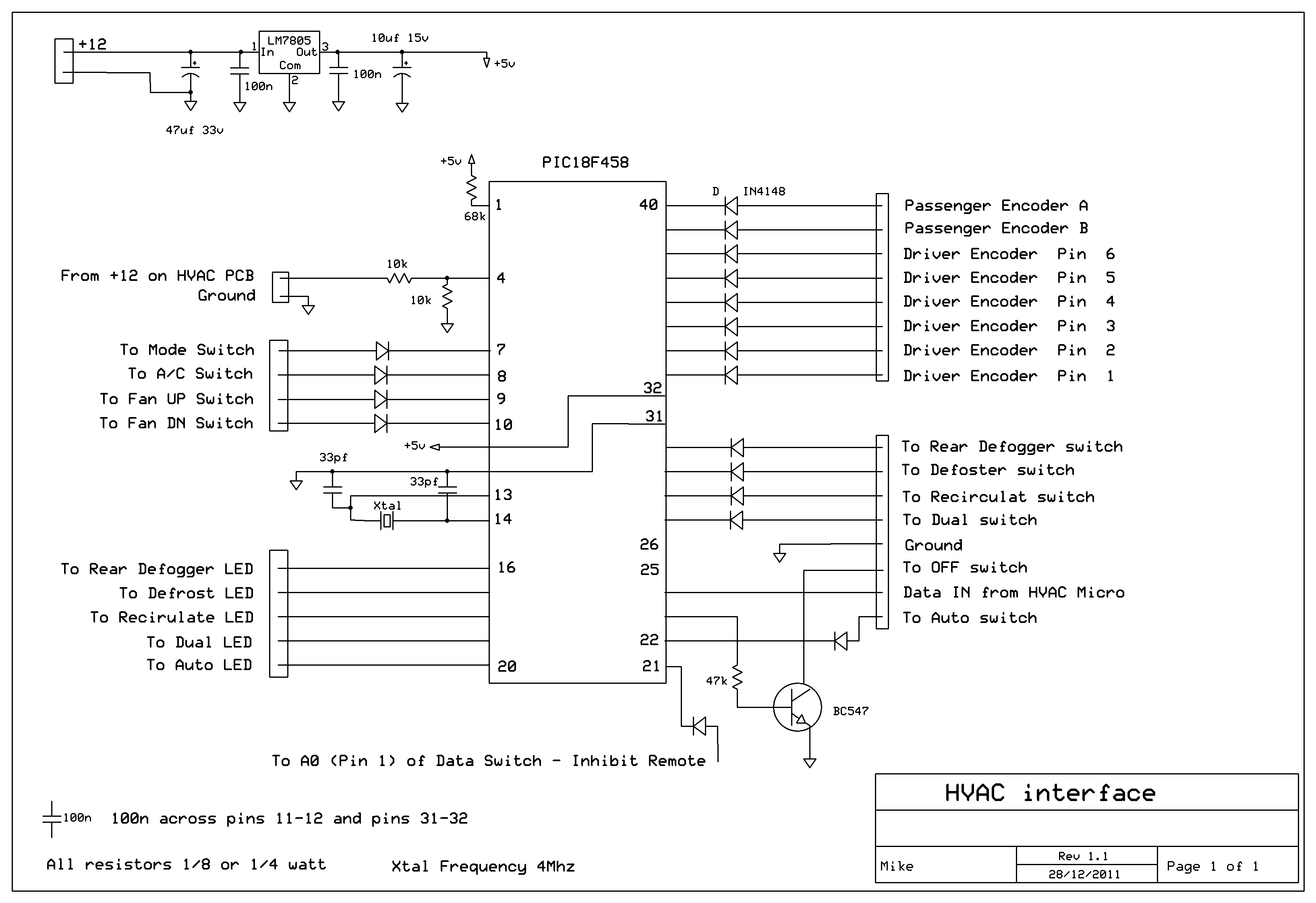
The first unit connects across the existing PCB mounted control buttons on the main HVAC PCB. It has a serial data connection via Pins 25 and 26. These can connect to a PC or in the case of a simple stand alone system are connected to the 2nd unit which is the remote HVAC control circuit.
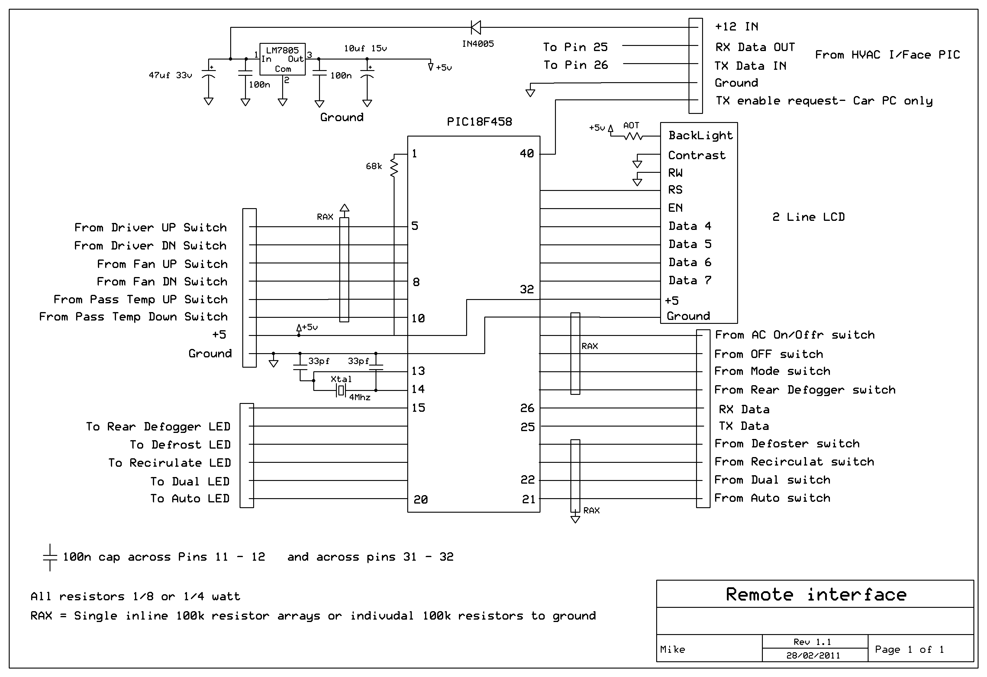
The remote unit connects via 4 wires - 1: 5 volts, 2: Ground, 3: TX data and 4: RX data - and it only needs some push buttons to control the HVAC system. It incorporates a small low cost 2 Line LCD to display HVAC status. Both these units have been running for years without a single glitch or fault.
This system allows you to relocate that big HVAC PCB out the way and the only connections between the control buttons (in the remote) and the HVAC board (with the first interface PCB connected and mounted with it) is the 4 wires mentioned above and these can be in a very long small 4 core cable.
The first unit connects across the existing PCB mounted control buttons on the main HVAC PCB. It has a serial data connection via Pins 25 and 26. These can connect to a PC or in the case of a simple stand alone system are connected to the 2nd unit which is the remote HVAC control circuit.
The remote unit connects via 4 wires - 1: 5 volts, 2: Ground, 3: TX data and 4: RX data - and it only needs some push buttons to control the HVAC system. It incorporates a small low cost 2 Line LCD to display HVAC status. Both these units have been running for years without a single glitch or fault.
This system allows you to relocate that big HVAC PCB out the way and the only connections between the control buttons (in the remote) and the HVAC board (with the first interface PCB connected and mounted with it) is the 4 wires mentioned above and these can be in a very long small 4 core cable.
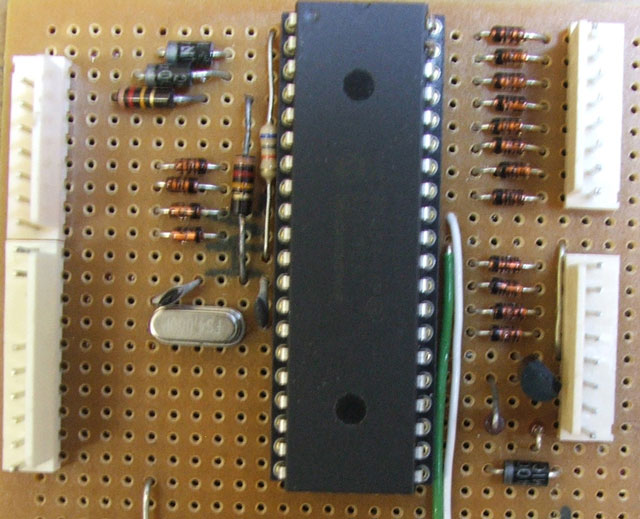
Prototype HVAC interface
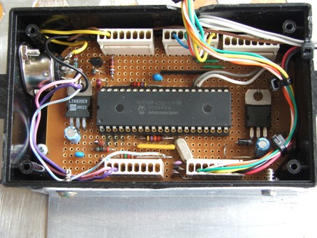
Prototype HVAC Remote


POS
|
PIN
1
|
2
|
3
|
4
|
5
|
6
|
LO
|
0
|
0
|
1
|
0
|
1
|
1
|
19
|
0
|
0
|
0
|
1
|
1
|
1
|
20
|
0
|
1
|
0
|
0
|
1
|
1
|
21
|
0
|
1
|
0
|
1
|
0
|
1
|
22
|
0
|
0
|
0
|
0
|
0
|
1
|
23
|
0
|
0
|
1
|
1
|
0
|
1
|
24
|
0
|
1
|
1
|
0
|
0
|
1
|
25
|
0
|
1
|
1
|
1
|
0
|
0
|
26
|
0
|
0
|
1
|
0
|
0
|
0
|
27
|
0
|
0
|
0
|
1
|
0
|
0
|
28
|
0
|
1
|
0
|
0
|
0
|
0
|
29
|
0
|
1
|
0
|
1
|
1
|
0
|
30
|
0
|
0
|
0
|
0
|
1
|
0
|
31
|
0
|
0
|
1
|
1
|
1
|
0
|
HI
|
0
|
1
|
1
|
0
|
1
|
0
|
HVAC/Radio control switches are Normally open with one side to ground and the other to +5 volts.
LEDS have +5 volts when active.
Passenger temperature encoder, is normally closed to ground (Pin3) and switches it’s encoder outputs to +5V on rotation. Standard Rotary encoder.
Driver encoder is a 6 pin device, output is a type of Gray-code.
Pin 1 is common.
Pins 2 to 6 produce a 5 bit binary code for 15 positions.
Driver Encoder truth table