My basic preposed means of interfacing to the Accord Dual Zone HVAC
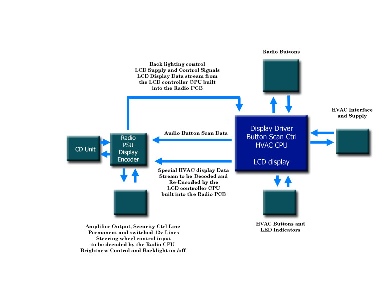
Here is a block operational diagram of the existing Dual Zone HVAC - Audio unit.
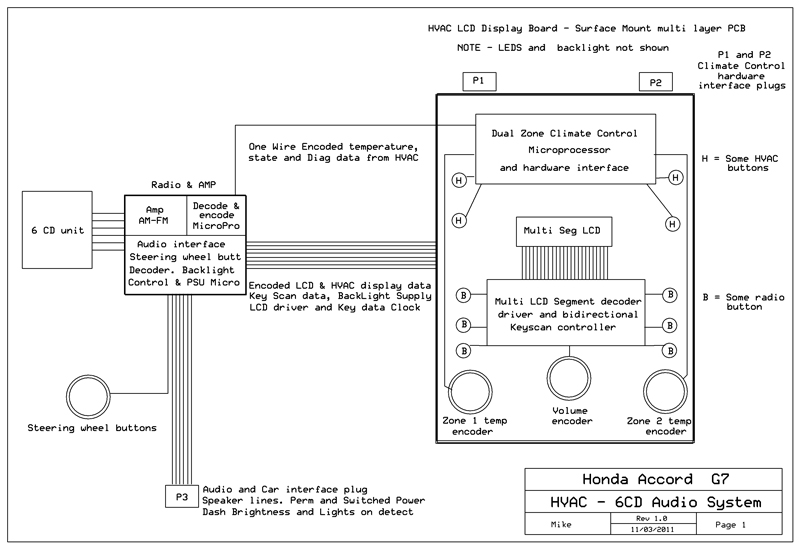
More detailed block operational diagram of the existing Dual Zone HVAC - Audio unit.
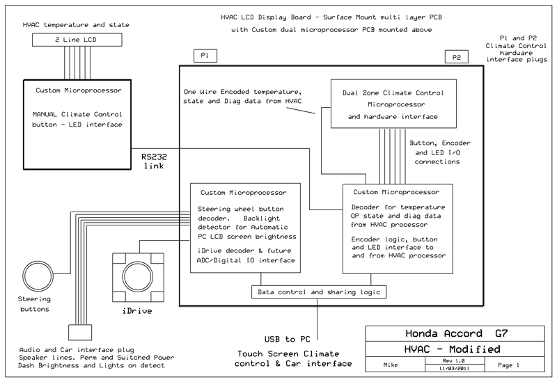
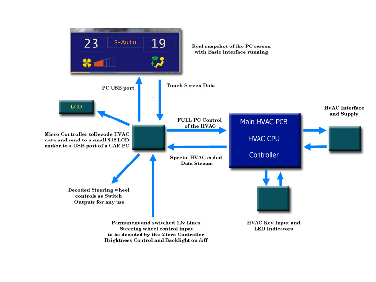
More detailed diag of basic preposed means of interfacing to the Accord Dual Zone HVAC
Dual Zone climate control and LCD Radio 6 CD stacker unit

This information may assist someone wanting to know how the HVAC - Radio/CD are interconnected and dependant on each for certain functions. This is a prerequisite if you are planning to remove or relocate the HVAC - Display PCB without using the Radio I did this a few years ago when I installed a CAR - PC with an 8" touch screen display and interfaced it to the Honda HVAC climate control system.
No one (apart from rumours) has successfully removed the combined “Dual zone climate control and LCD Radio 6 CD stacker unit” AND retained a fully functional climate control system, that last point is important. Single zone (non climate control) systems have been removed with aftermarket kits.
These basic systems leave a lot to be desired and work with of the shelf audio units. Basically a simple manual control of the basic single zone AIR-CON and a blank panel are supplied.Dual zone “full climate control” systems are a complex system in any vehicle and unless the system has been reversed engineered correctly it performs poorly or not at all. Many owners who purchased replacement aftermarket integrated NAV-Audio solutions from China supposedly made for the Honda Accord G7 have found this out the hard way.
The problem is twofold.
1.The LCD display is made up of a number of fixed graphic display sections. A few are for HVAC temperature display and operational status. The rest indicate 6 CD stacker status and AM-FM and Audio system information. The LCD module has over 75 connections to the PCB. Most people crack or shatter the module if they try to remove it without damaging the board. The Audio - 6 CD unit mounts behind the front panel display PCB - This is a very large multi layer surface mount design board, size is 7” x 10” and almost as big as the front panel. It incorporates a large fixed segment LCD with all radio buttons, audio controls, LCD interface, key scan controller, HVAC buttons and HVAC microprocessor Climate control systems spread around the PCB.
2. The LCD display and front panel were designed primarily as a split part of the Radio-Audio system. The microprocessor interface that drives display data, power supply and control of backlighting and control illumination and all data clocking/strobe signals are coded inside the Radio-Audio unit. The unit was obviously modified to take an undocumented single wire data stream (it took some finding) from the HVAC microprocessor and display it via the decoded/encode function in the radio. There are no circuits (that I have been able to find) for the HVAC-LCD PCB or Radio - Audio microprocessor systems.
Removing the Radio-Audio system from the front PCB leaves you with nothing except a functional but blind Climate control system; and a very large PCB that had to be relocated if you want to use the space occupied by the removed Audio system Doing so means that you no longer have any buttons or controls for the HVAC system as they are surface mounted on the main PCB behind the front panel.
Also shown below is the basic way I started with interfacing to the HVAC and audio system. Microcontrollers to the rescue.