


I have a car computer with GPS, DAB radio, Mobile Phone, Audio player with 1000's of songs, full HVAC climate control intefrace via 8" LCD touch screen, reversing camera, HI definition front and rear drive recording cameras and a control interface microprocessor for manual button control and steering wheel button control.
Due to annoying LCD Monitor backlight GLOW in pitch black driving conditions I set about looking at my LCD LED backlighting. I removed the monitor from the vehicle and was surprised to find that it did indeed adjust LED backlighting, however it’s only a 3 step adjustment for Bright, Normal and Dark and is automatically controlled via a small Photo Diode. It’s a PWM control from a small separate PCB labelled “funnily enough” LED DRV.
This LCD PCB has the standard 2 wires running to the backlight LED array and another small 4 pin connector. The 4 pins were earth, +5v, +5v and the other varied from 0.4 volts to 1.2 volts in response to the Light detector circuit on the Main PCB. Quick test and I found I could get the LED backlight to go way down in brightness with 1.8 volts (normally 1.2V at Dark setting) on that pin and brightness variation was linear with voltage from 0.4 to 1.8V.
Total display consumption @ 12V is 6 Watts with bright and around 2 Watts dim backlight.
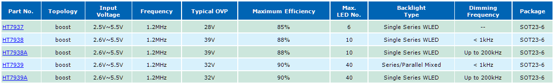
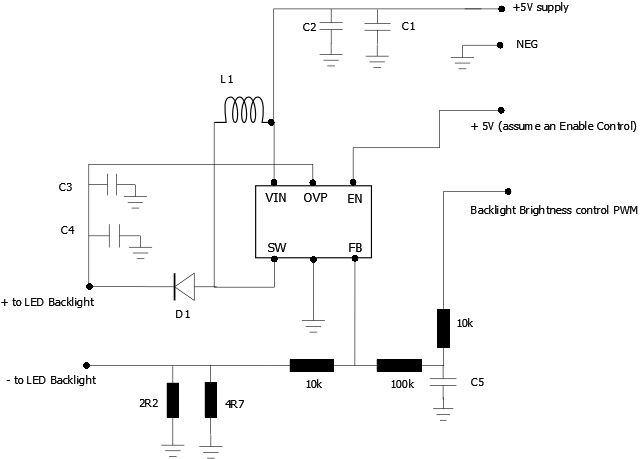
I traced out the circuit for the LED Backlight Control. The IC appears to be a small (SMD) 6 pin Step-up convertor. The current through the LEDs is sensed and SET by parallel connected resistors 2R2, 4R7. With this layout I would assume overvoltage protection, open circuit protection, over current protection etc.
Due to annoying LCD Monitor backlight GLOW in pitch black driving conditions I set about looking at my LCD LED backlighting. I removed the monitor from the vehicle and was surprised to find that it did indeed adjust LED backlighting, however it’s only a 3 step adjustment for Bright, Normal and Dark and is automatically controlled via a small Photo Diode. It’s a PWM control from a small separate PCB labelled “funnily enough” LED DRV.
This LCD PCB has the standard 2 wires running to the backlight LED array and another small 4 pin connector. The 4 pins were earth, +5v, +5v and the other varied from 0.4 volts to 1.2 volts in response to the Light detector circuit on the Main PCB. Quick test and I found I could get the LED backlight to go way down in brightness with 1.8 volts (normally 1.2V at Dark setting) on that pin and brightness variation was linear with voltage from 0.4 to 1.8V.
Total display consumption @ 12V is 6 Watts with bright and around 2 Watts dim backlight.
I traced out the circuit for the LED Backlight Control. The IC appears to be a small (SMD) 6 pin Step-up convertor. The current through the LEDs is sensed and SET by parallel connected resistors 2R2, 4R7. With this layout I would assume overvoltage protection, open circuit protection, over current protection etc.
Interesting Note: This monitor also adjusts the Brightness and Contrast levels along with the Backlight level with the 3 Step Ambient light sense circuit located on the Main PCB.
Currently my PC Front End software is programmed reads the Honda Accord PWM dash-light signal and adjusts the Windows brightness level, this works well in conjunction with 3 step Auto Backlight on the Monitor - however it is STILL not quite enough for country night driving and this is where further reduction of the LED backlight will make a big difference. My initial interest in Backlight control was in the hope it would maintain good contrast and colour depth at low output levels, which is not always the case with trying to bring Brightness and Contrast way down with normal controls and via the Windows API.
Test carried out last night appear to indicate this is a far superior method and I had really good colour and contrast with the LED backlight wound way down. I was trawling the NET trying to find an IC/circuit similar to the one I traced from the LCD PCB. There are some very complicated LED backlight driving schemes out there but mainly for large screen devices, haven’t found anything much like this as yet until this.
Note: My unit is PWM and not DC on the FB control input. But DC control worked perfectly, after the filter (C5 and input resistor) PWM would be converted to a DC voltage anyway.
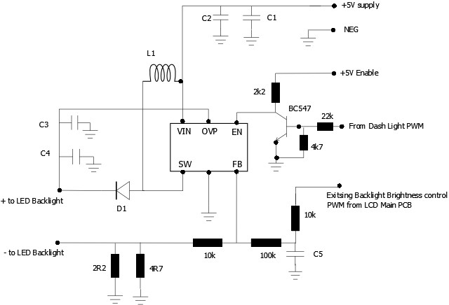
I modified my LCD backlight PCB for direct control of the LED backlight by the Vehicle dash-light PWM signal.
The PWM control in the G7 Honda is a 200HZ PWM square wave running at 10v Peak.
Dash-light control full brightness: PWM stops and Line drops to 0 volts.
Dash-light control 90% brightness: PWM around 10% on 90% off
Dash-light control 50% brightness: PWM 50% (1:1) or 50% on 50% off
Dash-light control fully dimmed: PWM around 90% on 10% off
This is of course the opposite to what is needed to Drive the Enable/low freq PWM line. IE +5v is applied by the current LCD controller for full Brightness (Enabled) and 0V is off (Disabled). However, it is absolutely perfect for allowing me to keep the existing Enable control from the LCD PCB which is used to turn the Backlight off when no video is present.
The modification required one NPN transistor to invert the waveform and 3 resistors. Two resistors are used to drop the 10v PWM down to the correct voltage to drive the transistor and the 3rd resistor (2k2) is used as the load resistor between the existing +5V Enable Line and the collector of the transistor. Almost no way to damage the LCD or controller this way as the only connection is via a 22k resistor.
So, dash-lights OFF = no voltage to the transistor, so it’s switched off and as before, the Enable line is controlled by the LCD main PCB. Dash-lights ON and the PWM signal controls the Backlight, the Enable Line can still kill the Backlight in the absence of Video or in standby.
I have left the existing backlight control from the LCD Main PCB as they work perfectly together.
When installed in the Vehicle it is perfect!
1. With the LCD backlight controlled by the vehicle dash-light, which is controlling the modified PWM input, AND also using the LED 3 step Backlight control built into the Monitor, the result is “almost” perfect in a pitch black location with no annoying GLOW effect.
With only that control, normal driving with streetlights and other vehicles would be perfect.
2. In complete darkness - no street lights or other vehicle headlights - like night time country driving.
With 1 (above) and my Front End software ALSO controlling the Windows brightness via the API, as most FE application seem to do, the extra reduction in brightness results in a perfect display, again without that annoying GLOW effect from my normally half lit backlight. I can only imagine how annoying a full lit backlight would be in an 8” screen that’s not far below eye level.
Finally, if you have a monitor that doesn’t control LED Backlighting, and it seem there are a lot that don’t, then the effect will be even more dramatic. At least my unit dropped the backlight to 50% at night, but as I said, it was still a bit annoying in really dark driving conditions, now it's perfect

Just to clarify a few things here.
I have been reading through some of the old threads on LED Backlighting control and the means used to attempt to control them. So here are a
few points to consider when using this circuit.
1. May already be inside your Monitor and only needs a simple mod for external control.
2. The circuit can be controlled by either a PWM signal or a variable DC voltage.
3. The voltage across the LEDs is DC when the IC is controlled with a DC voltage via the FB pin.
4. The voltage across the LEDs is of course PWM when the IC is driven with a PWM signal via the Enable pin.
5. Can be driven straight from a Microcontroller with PWM into the Enable pin.
6. Parts don’t have to be SMD (except for the IC) but that is only a 6 pin device and the spacing is pretty reasonable, soldering with a fine tip iron
would be relatively easy, if you have soldered before.
7. No heat-sink required and very small size.
8. Can be interfaced to the existing Vehicle PWM line with minimal effort and $1.60 in parts.