


The Big Cap - HF Copper Loop for 40, 80 and 160m
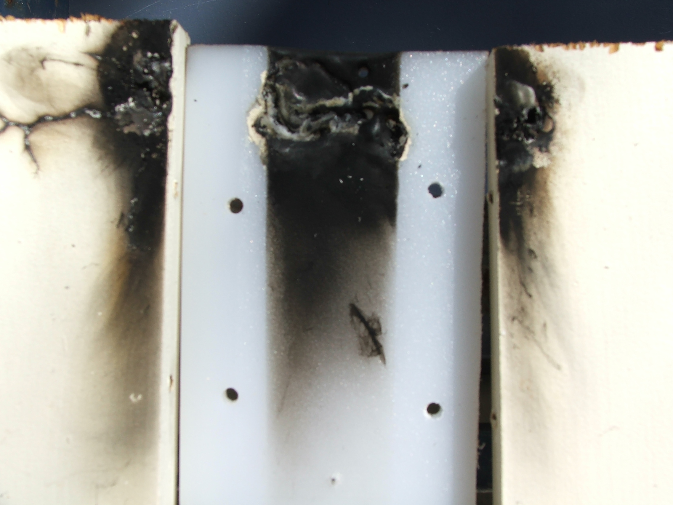
You can see the burnt assembled support block mounted at the Loop top. The Loop has been tilted over and is pointing down.
This entire assembly is covered with a plastic case. The initial spike caused a track and then running at around 100 watts trying to find the fault did the rest.
This entire assembly is covered with a plastic case. The initial spike caused a track and then running at around 100 watts trying to find the fault did the rest.
Is there really a high voltage at the top of the loop?
The Pictures below were taken when the small cap was still in use. With the new cap and almost 6 inches of spacing for the support block this should never happen again. It should never have happened anyway. I guess there must have been a bit of moisture or contamination on the board
The burnt gap between the timber supports is 35 mm. Power spiked to 900 watts when the drive was accidently set high during testing.
The piece of Polypropylene cutting board had been tested in a microwave for heating before I used it here.
tried to fit on this block, I still have the log entries. Except for the VK3 in Melbourne I was the strongest station by about 6dB into New Zealand
with my 80 watts. I was the same or slightly stronger than my friend 15km away to most other stations, he is using a full size dipole at 40ft and
next to the ocean. Except for one vertical all other stations were using dipoles, some at 70 to 80 feet and one or two stations were running a few
hundread watts.
The other point is that the station local to me always received everyone at least 6dB to 10dB stronger than I did, as had most of the stations on the net. Looking at the logs going back for quite a while, this has always been the case - until now! This time the signals received my me were the same or stronger that the signals my friend was receiving and I was receiving the other stations as strong as or sometimes stronger than the others were reporting, especially the distant stations. The loop allowed me to null a +15 power pole discharge that's over 500m away and take it down to below my s5 noise floor, which would have been +20dB on the vertical.
I am out of answers? I expected 40m to be good, I was wrong, it is fantastic. I thought 80m would be passable, wrong again, the usual quote I get is "don't touch anything whatever you're doing it's really working, big signal", but 160m was only every intended (as I was led to believe) to give me a few local contacts, if that. After all, the loops calculated efficiency is 7% and it's around 1/14th of a wavelength on 160m.
It's only 3.6m high and mounted 2m above the roof of the shack. A lot of folk work 160m DX mobile, but in good conditions so I guess it's possible. I just expected a really big difference between some of the full size aerials and my tiny 160m aerial. Maybe I just got lucky last night :>) I will see how and if it holds up over the next few weeks.
UPDATE 1. A few weeks later and the reports are the same. I am still equal to the fullsize dipoles at low heights on interstate and local contacts.
Is a 160m dipole at 40ft like a 10m dipole at 2.5 ft? UPDATE 2. Six months on and still one of the strongest signals on the 160m and 80m nets.
I must point out that the coax to this aerial has only 2.1m exposed outside of the shed: It runs straight down from the loop through the steel roof of the shed. It is clamped against a 100m grounded steel mast that runs through the roof of the shed. The mast is grounded by 6 ground wires terminated with 6 individual 3m copper ground rods around the perimeter of the 6x9 shed. The shed is also grounded and the rig and equipment have separate grounds. The coax inside the shed is 4m long and runs over the top of the micro controllers that tune the loop. There is no sign of any RF induction into the sensitive micro equipment even with full legal power. All power to the shed is underground.
If anyone seriously thinks that 2.1m of coax strapped against a 1.2m length of 100m "square tube" grounded pole is aiding or causing the RF to radiate on 160m then they are seriously deluded!
I called a friend who is about 20km away. My receive signal to him was s9+10dB and his
signal was around s9+15dB. The purpose of the test was to see the difference rotating the
loop made to close by signals.
Our signals went down around 15dB in the null of the loop, so most of the signal from him was above 30deg, some days it can be as much as 20db or as little as 10dB. His antenna is a dipole at around 45 feet which is great for running the local NET on 160m as NVIS is what you want in this situation.
Made contact with two stations that I have been trying to work for a few years now at 3.30pm on 1.840 mHz. I could only ever hear bits of the conversation and they could never hear me on the vertical or inverted-L. One was s9 to s9+10dB and the other was s9+5dB, they received me s9 to s9+10dB. I was back on the air on 160m.
The tuning does not change with heat or power. The bandwidth is very narrow though at around 1.6khz. However the signal sounds fine on air and the rig runs full power although
the SWR meter on the rig jumps up to around 2:1 as I talk.
I found that on 160m I have to tune lower in frequency to place the sideband into the band-pass of the loop. I can rock the rotary encoder as I talk and fine tune the SWR to stay fairly steady with voice on 160m. Everyone reports very good audio.
_______SWR|__2__|_2.62|__3__|_Band_|
Bandwidth | 1.6k| 2 k | 2.1k| 160m |
Bandwidth | 4.5k| 5.8k| 7.5k| 80 m |
Bandwidth | 25k | 26k | 30k | 40 m |
My big test comes when I join the Monday night net in 3 days time. At least a few of the guys should hear me and this time I should be able to hear almost everyone.
UPDATE
Called into the 160m net with 13 stations from New Zealand - 2300 km away -, VK3 and Charters
Towers in the north. eleven stations were in VK4 with one 15km away. I have worked these
stations on this net numerous times before on an inverted-L and different verticals that I had
The Q of the loop changed when the big vacuum cap was fitted. It is now slightly higher. The
gamma match now matches at less than 1.26 to 1 from below 160m to above 40m.
Why did the Q change with the bigger vacuum cap? Could it be less resistive loss due to the bigger surface area and larger physical connection area? Once again it shows how important the tuning capacitor is to the loop. I believe that it is one of the most important links to efficiency, ease of use and performance in a small loop.
This loop is about 1/13th of a wavelength on 160m and the calculated efficiency is very low at around 7 to 8% (Using common incomplete loop formulas) So how did it go on air?
It was a very noisy day when I first tried it with the new vacuum capacitor. I had a s9 + 10dB static like power line discharge noise. I rotated the loop to N-S and the noise went down to meet the S5 normal background noise I get in suburbia.
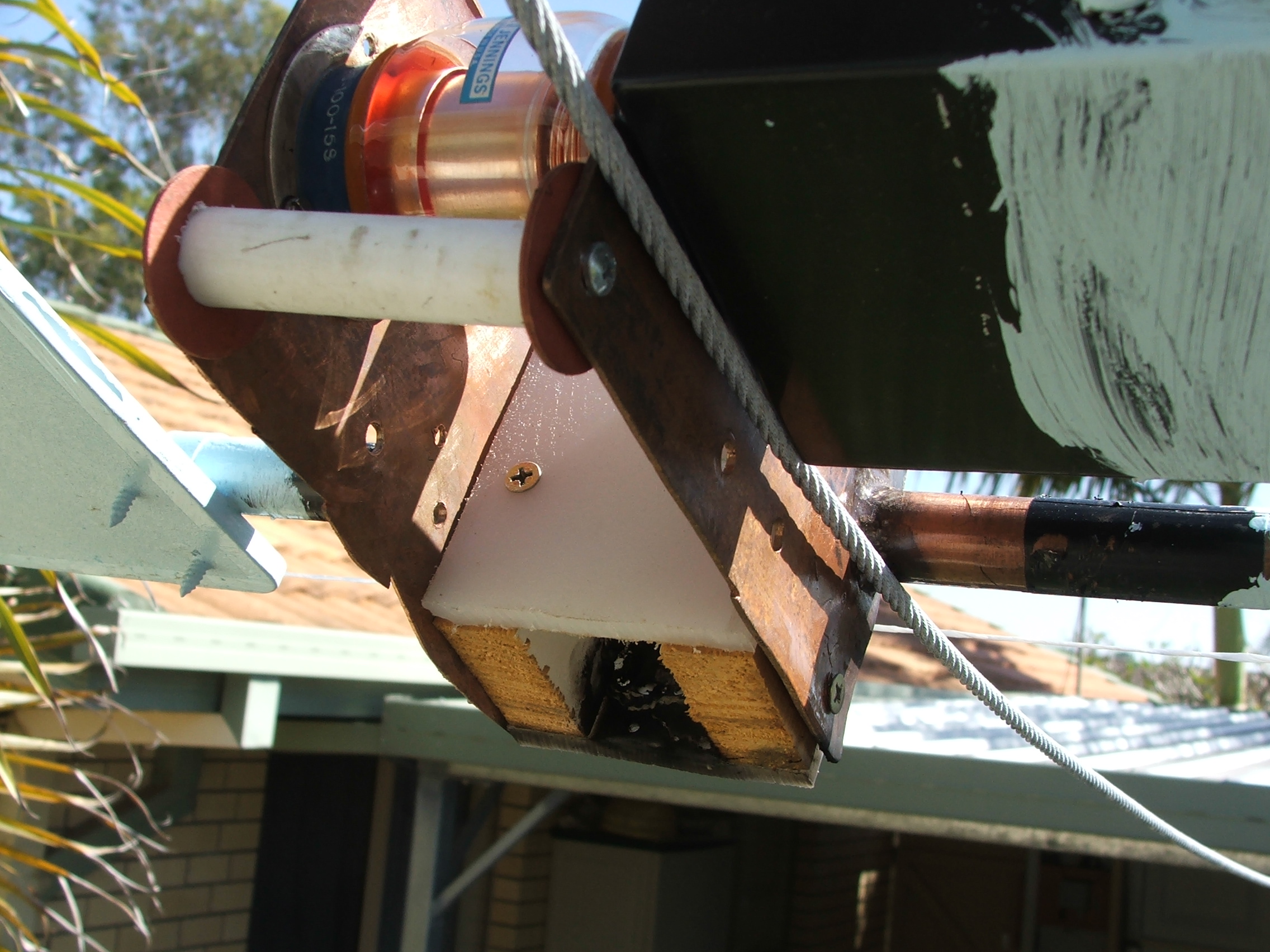
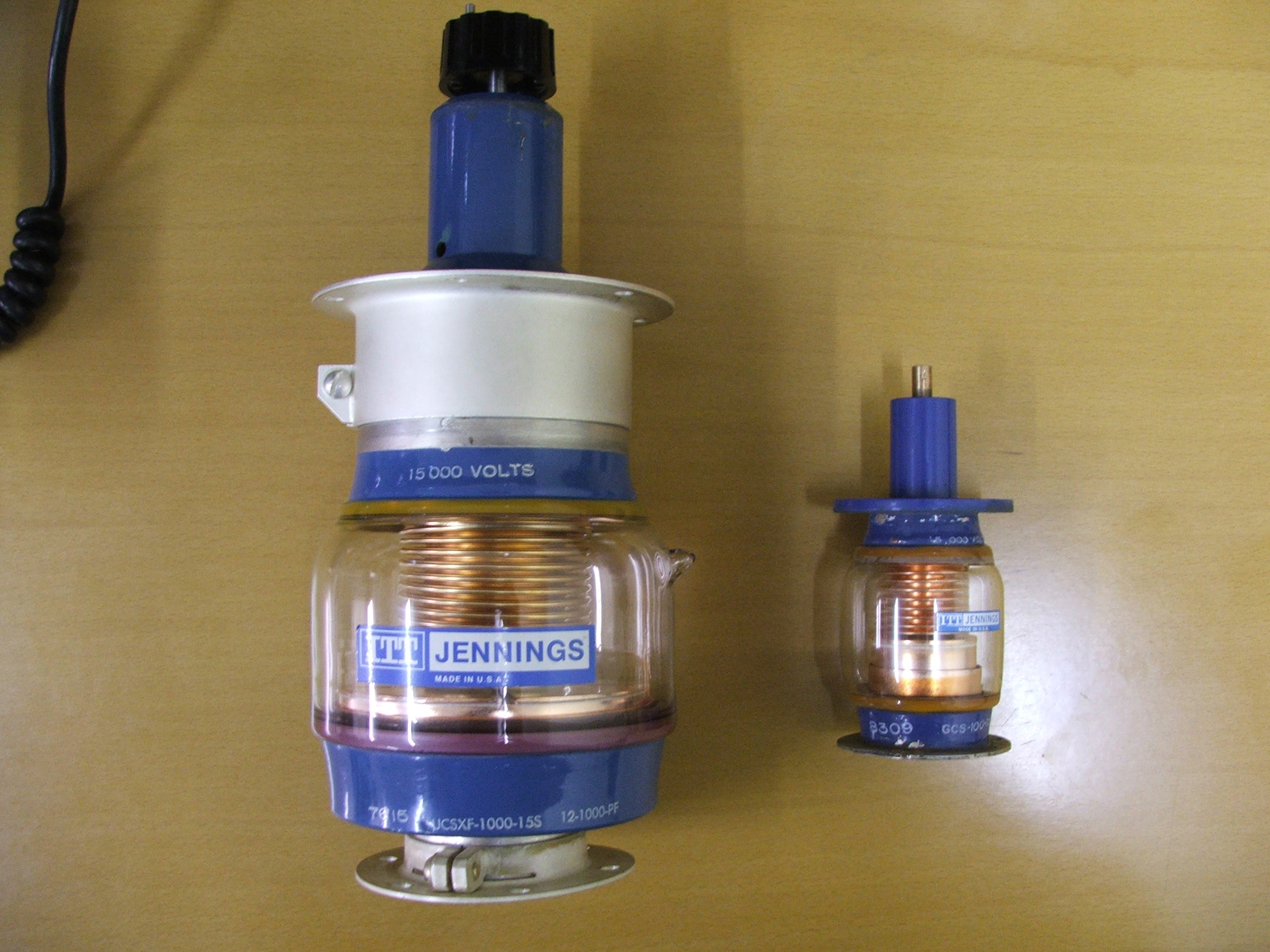
I received my new 1000pf 15kv Vacuum capacitor and fitted it to the Loop. It dwarfs the tiny 100pf 15kv capacitor I had been using. This unit
is around 10 inches long 4.4 inches wide and weighs in at over 4lbs. The spacing between the copper mounting plates at the top of the loop has
been widened to 6.5 inches to accommodate the capacitors mounting flanges.
A 6:1 reduction drive has been fitted between the stepper motor and the cap. This bought the resolution down to around 0.02pf per step which is needed for easy adjustment of the loop. The cap has 40 turns lock to lock to cover 12pf to 1000pf or about 25pf per turn.
The stepper has 200 steps per revolution (1.8 deg) and with a 6 to 1 reduction drive this translates to 1200 steps per revolution. One turn of the cap is 25pf so 25 div by 1200 is about 0.02pf per step. The encoder has 24 steps per revolution so 1200 div by 24 equals 50 turns of the encoder to rotate the vacuum cap one turn. With fast fwd / rew buttons it takes around 40 seconds to go from 40m (27pf) to 160m (560pf) but only a few seconds to go between 40m and 80m - 27pf to 150pf.
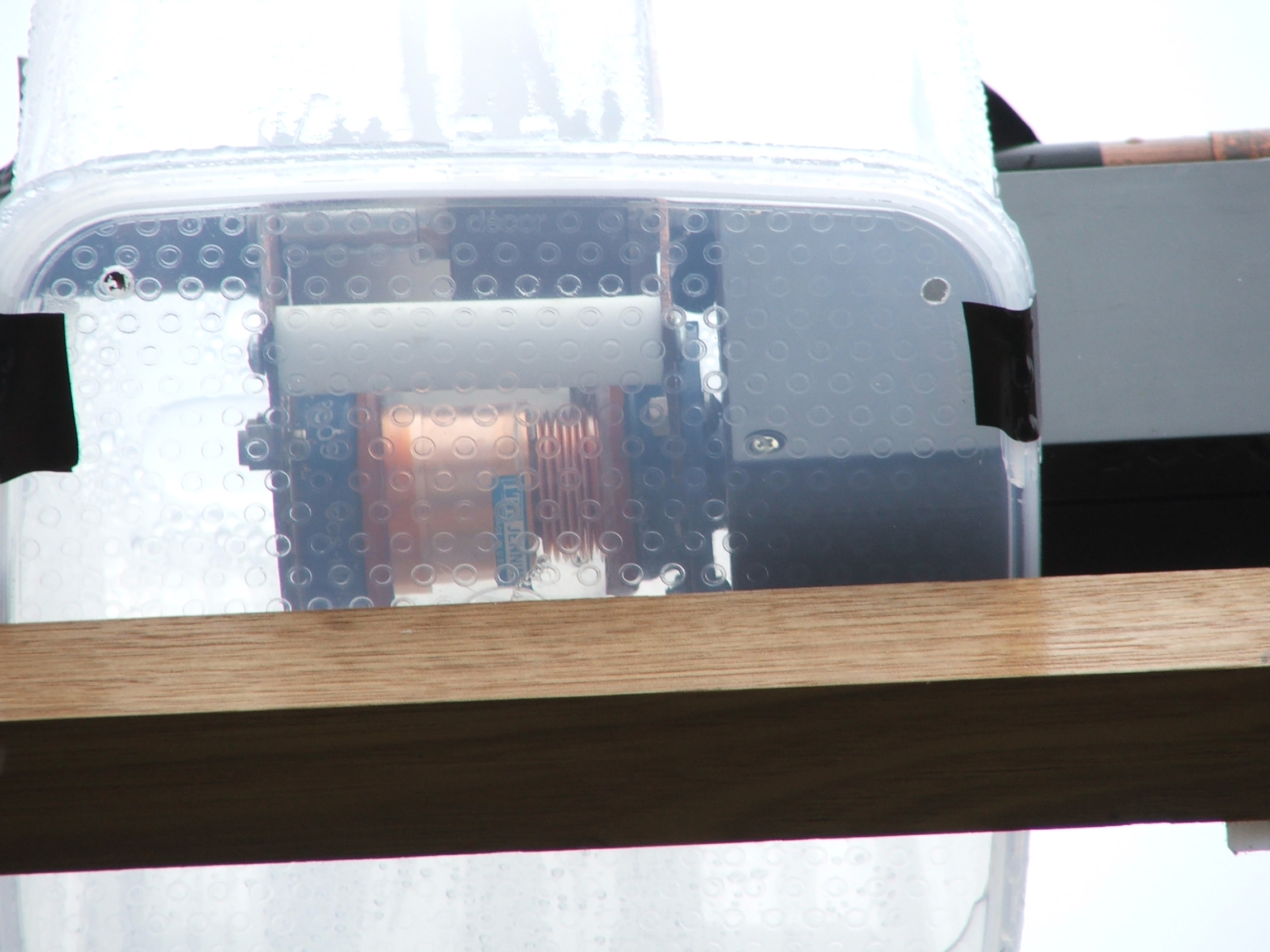
The 1000pf vacuum mounted on the loop
Small 100pf vacuum cap on the loop
Click Image to
enlarge