


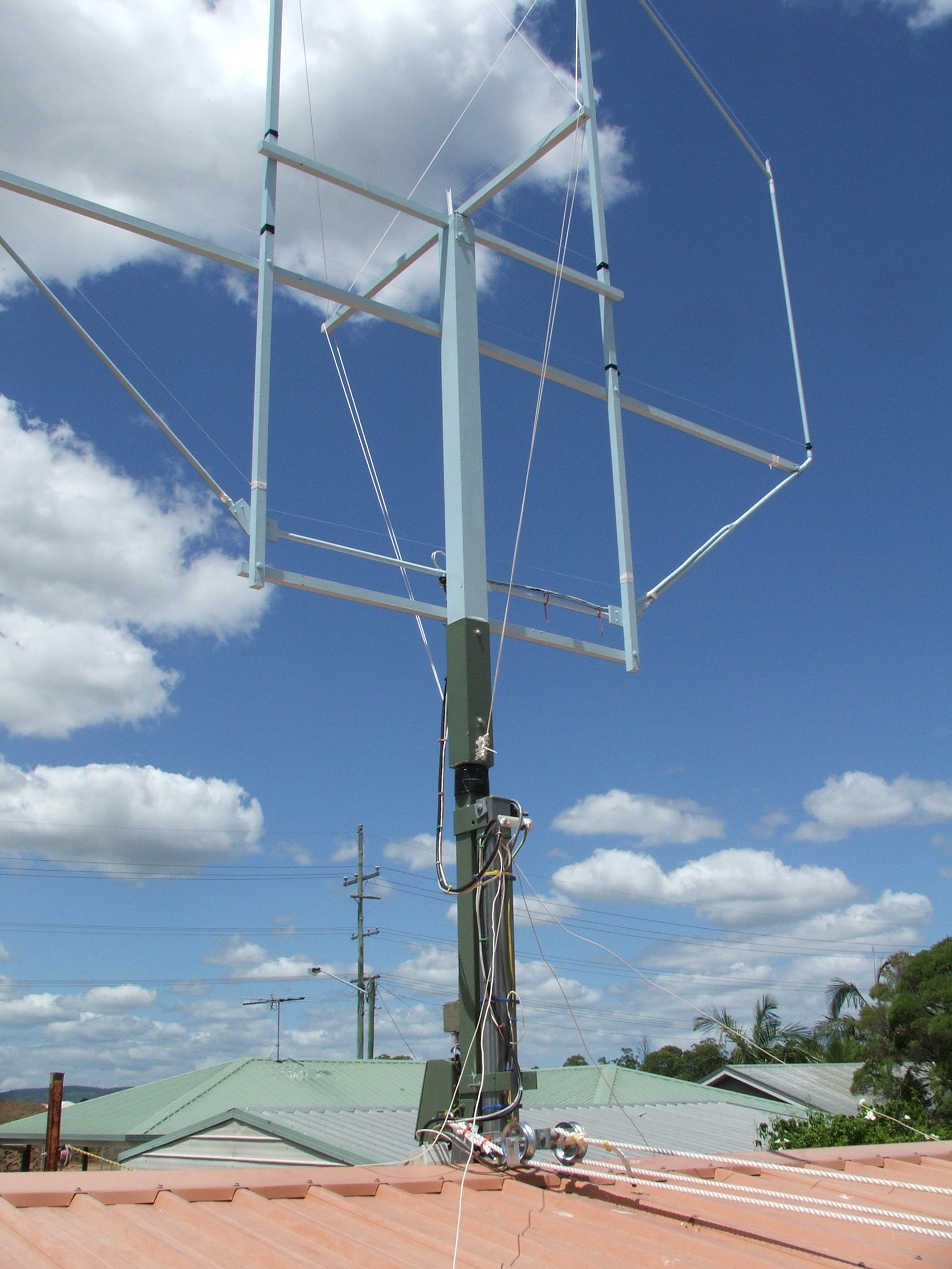

Eight months on- The Loop after eight months in the elements.
You will notice a cross beam has been fitted half way up the loop. I found that
with the heaver vacuum capacitor and a 6:1 reduction drive that the loop would
get a sway at the top under gusting winds. It also takes the weight when the
loop is tilted over and removes any bending of the two vertical support poles. This
was a simple modification that took less time to fit than it did to paint the timber.
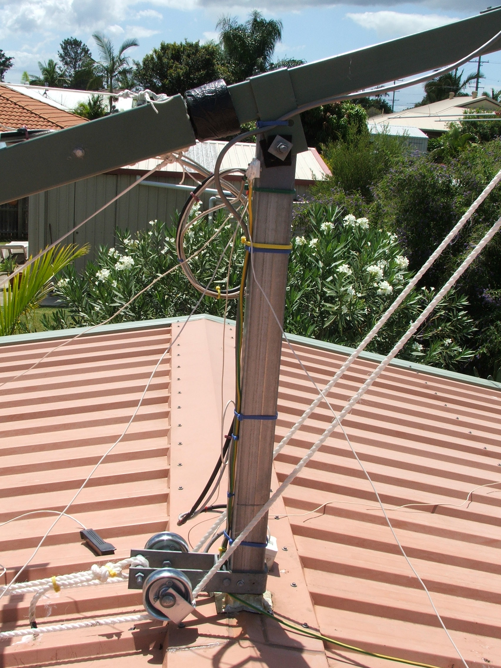
I used 2.5mm VB cord, available from most marine stores such as B.C.F. The cord is attached with stainless steel cleats screwed to the steel box section at the base of the aerial that holds the main 90mm square vertical timber support. The added timber pole is offset to favour the side of the aerial that is on top when
tilted over - In other words more leverage to counter the weight on that side.
You may notice a few plastic vertical risers at the top of the loop; these hold clear fishing line that I used to stop most birds landing on the loop, its surprisingly effective; the main reason for doing this was to protect the roof of the shack.
The copper tube and timber are as good as the day I painted them, there has been no deterioration anywhere on the loop. The aerial still tunes to 1:1 and the gamma match has not been adjusted since the antenna was commissioned.
For those interested; The timber used in the frame of the loop is 32mm x 32mm dressed hardwood. This particular timber - I have no idea what type - is quite light for its size and very stiff compared to almost any other timber that I could find at the local hardware. However when designing the loop I had not thought
of fitting a support pole (as I have now fitted) and guying the top of the loop in such a way as to allow it to be free standing, rotatable and still fold over. There should be no problem now using timber that has less tensional strength.
I spent over twelve months researching loops and trying to come up with a way to make it completely freestanding. I was determined to exploit the ability of the loop to null interference, therefore it had to be free to rotate 180 deg. I knew from past experience just how strong the winds can get here so the antenna had to be constructed to allow for easy tilt over and it was to be mounted on the roof of my shack. This all seems so easy in hindsight; it was not!
The biggest stumbling block was the having to mount the capacitor at the top of the loop. There is quite a bit if leverage generated with that weight at the end of a 3.6m fulcrum. Would I do anything differently if building another? Absolutely not!
There are no problems with this design, the only changes made were the extra tension bar and guys that were added to handle the weight of the heaver vacuum capacitor and add stability in strong winds. The ability to quickly tilt the antenna over to work on the vacuum capacitor and drive motor or to check and maintain the condition of the antenna when needed, is a must.
There is a lot of leverage required to tilt this antenna. The tilt point is one meter form the base of the aerial, leaving one meter on the other side of the tilt point to raise the 4.6m length of timber mast, copper loop, timber frame and eight pounds of weight at the very end caused by the vacuum capacitor and drive motor.
The antenna is lowered and raised using a low cost electric boat winch - a hand winch worked fine. It takes about twenty seconds to lower or raise. I will post pictures of the simple counter-balance and pulley system I made to accomplish this at a later time.
NOTE: If the Quicktime movie does not play in your browser. Right click on the button above and select "Save target as" Save the file to your
Hard disk and then click on the file to play - file size is 7.3MB. The Video shows the loop rotating - The loop is paused for a second during the
rotation.
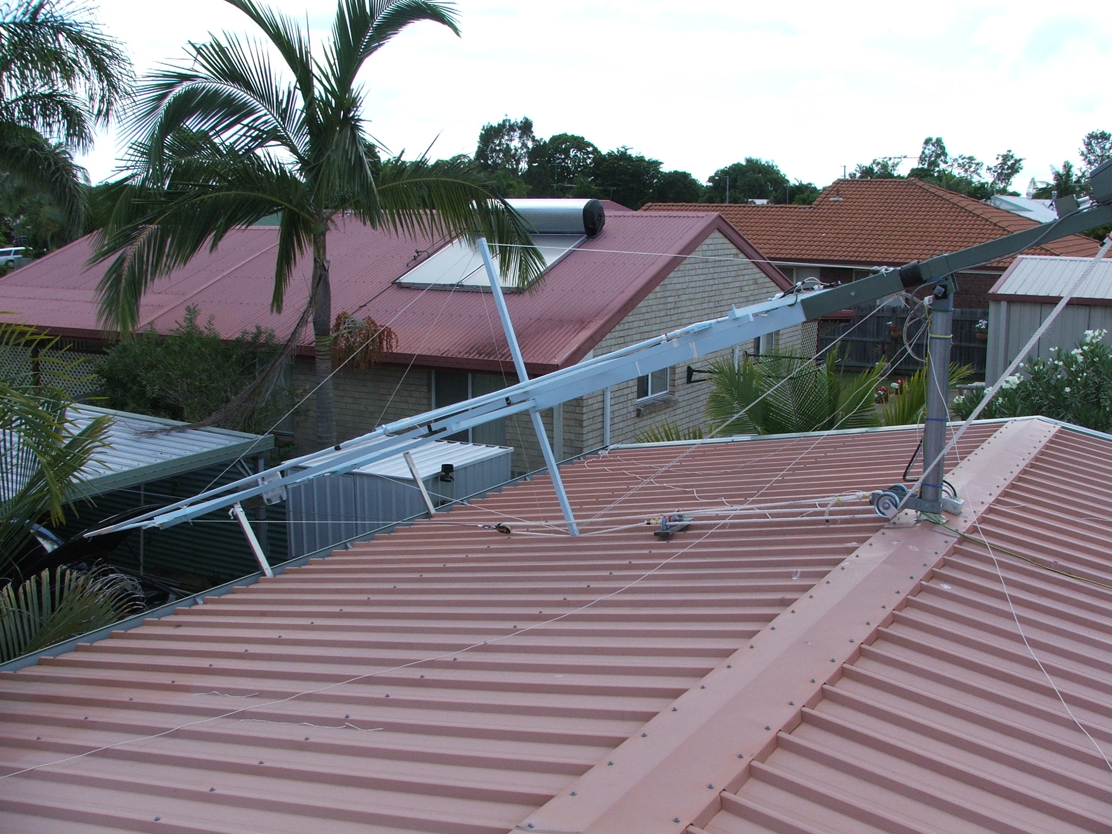
Storms, storms and more storms, the loop has survived. I am glad that I tilted it over before we were struck with 115kmh winds that caused the damage reported on national television. I had two minutes to spare after realising we were about to be hit. I think I broke my record of twenty seconds to lower the loop over, it later floated horizontally in the air as it was lifted off its resting pads with the force of the howling wind.
Storms, storms and more storms, the loop has survived. I am glad that I tilted it over before we were struck with 115kmh winds that caused the damage reported on national television. I had two minutes to spare after realising we were about to be hit. I think I broke my record of twenty seconds to lower the loop over, it later floated horizontally in the air as it was lifted off its resting pads with the force of the howling wind.
The Spectrum Analyser display is a capture of the receive
loop bandwidth on 160m. The scan was taken with the
main loop antenna connected to the RF input port of the
analyser.
The Tracking generator output was connected to a small loop probe mounted six meters away on-axis with the main loop antenna.
The following results were measured in the near field of the antenna and therefore not an accurate representation of the true bandwidth or directivity of this antenna. Tests will be made in the far field when time permits me to finish the remote telemetry field strength equipment.
The Spectrum analyser is set to 1dB per division vertically and 2 kHz per
division horizontally. The selected filter bandwidth is 50Hz.
This measured bandwidth on the analysers digital readout is 2.99 kHz at the 3dB points. The 2.62:1 SWR bandwidth using a network analyst is 2 kHz.
The Null depth cannot be measured past 25dB as the signal completely disappears into the background noise when the antenna is rotated the last few degrees - A very sharp final null with at least a 25dB null measured.
Note - This is Nowhere near the noise floor of the Spectrum analyser. The limitation is caused by insufficient signal from the tracking generator.
The aerial tilted over - The 4 wires coming away from the mast, just below the tilt point, were used when I was testing for variations in SWR with
radials placed at different heights above the roof. It gave me some idea as to the roof effectiveness as a ground plane.
Not shown is a rope coming from the back of the Rotator housing. This runs down to a pulley on the roof (just out of site in the above left picture) and then to another pulley on the edge of the roof then down to a 30kg weight. This leverage point pulls the tilt section away from the vertical position when lowering the antenna; it then starts to counter balances the movable mast section as it begins to tilt over. I can raise this aerial by hand by lifting the aerial half way along and walking it up - I use the winch though. The fixed 3.4m long 100mm square steel mast runs through the roof of the shed and is bolted to the floor. It is bolted just below the roof line to one of the four 200mm wide steel C section A frame supports.
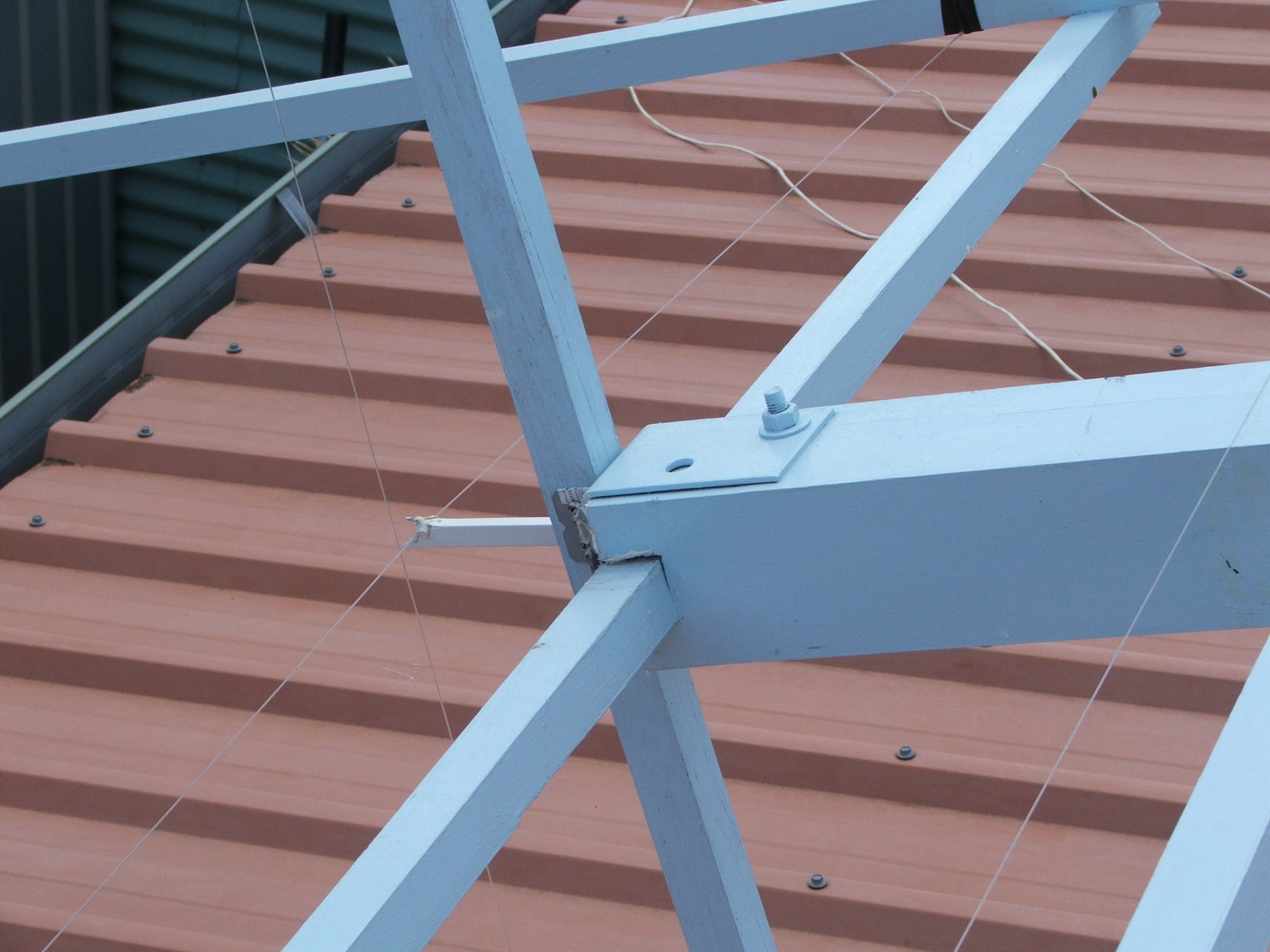
The bottom right picture is a close up of the cross beam and construction at the top of the 90mm square pine support mast. The plastic riser holds the fishing line above the beam to stop birds landing - Works for a lot of the birds.
Not shown is a rope coming from the back of the Rotator housing. This runs down to a pulley on the roof (just out of site in the above left picture) and then to another pulley on the edge of the roof then down to a 30kg weight. This leverage point pulls the tilt section away from the vertical position when lowering the antenna; it then starts to counter balances the movable mast section as it begins to tilt over. I can raise this aerial by hand by lifting the aerial half way along and walking it up - I use the winch though. The fixed 3.4m long 100mm square steel mast runs through the roof of the shed and is bolted to the floor. It is bolted just below the roof line to one of the four 200mm wide steel C section A frame supports.
The bottom right picture is a close up of the cross beam and construction at the top of the 90mm square pine support mast. The plastic riser holds the fishing line above the beam to stop birds landing - Works for a lot of the birds.
Click Image to
enlarge