


Home Brew RF Bridge
Click Image to
enlarge
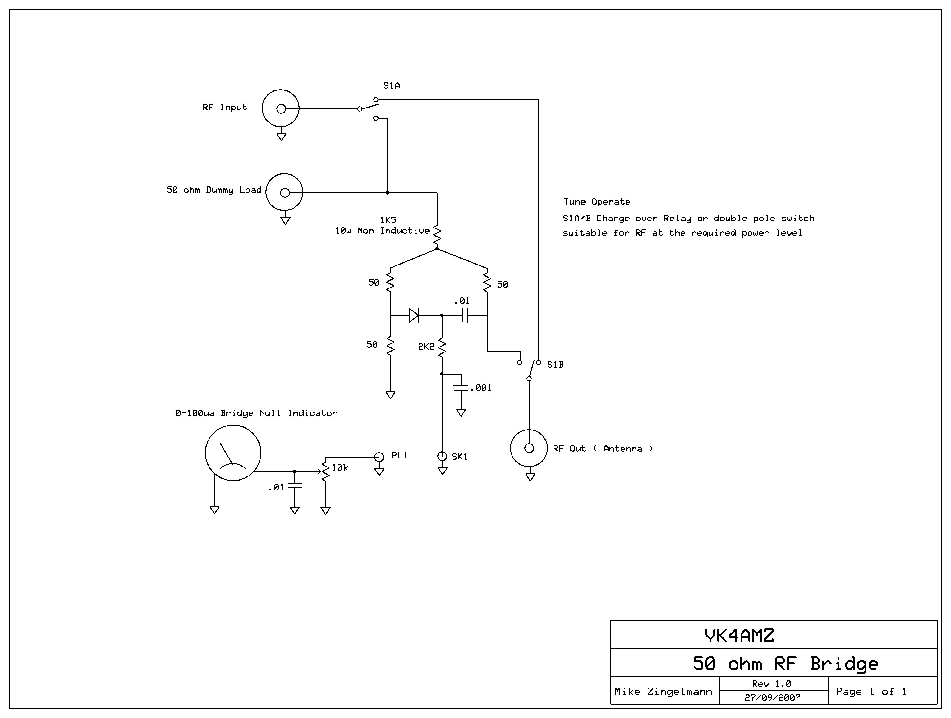
This RF bridge allows you to tune up on air with almost no signal.
The relay or switch must be wired up with RF in mind. You want to try and maintain 50 ohm impedance from the input to the output connector.
The 50 ohm resistors can be two 100 ohm ¼ watt in parallel. All resistors should be non inductive.
The bridge section should use very short component leads and should be shielded if possible.
One idea is to place the 3 x 50 ohm resistors the diode and the .01 connected to the diode in a small enclosure made of pieces of copper PCB. The lead from the 1k5 10 watt resistor can enter "through" a small hole in one side and the lead "from" the 2k2 resistor can exit through another small hole on the other side of the enclosure.
When the antenna impedance matches 50 ohms the meter will read almost zero, if the bridge is not built correctly full balance may not be achievable.
A diode with as little forward voltage drop as possible should be used however most small signal diodes should work.
If a sensitive meter cannot be found then a small op amp circuit can be used to drive the meter.
This circuit is built in to my home brew directional coupler / dummy load
and is used to tune the loop with only a few milliwatts of RF going to air.